Using CCDF As A Method Of Measuring P1dB And P3dB
By George Bollendorf, Empower RF Systems

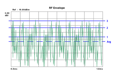
Understanding CCDF curves plays a crucial role in signal analysis, particularly when examining digitally modulated signals. The power-versus-time plot showcases the complexities of a signal's in-phase and quadrature components. However, decoding this inherently random and inconsistent signal necessitates a statistical approach, and this is where the Complementary Cumulative Distribution Function (CCDF) curve becomes invaluable.
A CCDF curve offers insights into how much time a signal spends at or above a given power level, aiding in the extraction of meaningful information from the noise-like signal. This article delves into the practical application of the CCDF method to define output power parameters, specifically the 1 dB compression point (P1dB) and P3dB. The discussion encompasses the challenges posed by soft compression characteristics, the advantages of utilizing a CCDF curve over traditional small signal definitions, and a step-by-step process for accurate measurements.
Through practical examples and considerations for complex digital waveforms, this article unfolds the effectiveness of the CCDF method in analyzing amplifier compression characteristics and peak power capabilities. By eliminating the need for a subjective small signal reference gain, the CCDF method emerges as a reliable tool for accurately determining compression points in diverse amplifier scenarios.
Get unlimited access to:
Enter your credentials below to log in. Not yet a member of RF Globalnet? Subscribe today.
