
Understanding 5G Millimeter Wave Beamforming Test
By Jeorge S. Hurtarte and Vito Liao, LitePoint Corporation

5G devices operating at millimeter wave frequencies contain two or more tiny antenna arrays, each array containing four or more patch antennas. The spatial beam direction of the antenna array can be changed on the fly by simply changing the gain and phase of each patch antenna. This dynamic change of the beam direction is called beamforming, and beamforming performance needs to be characterized in the R&D lab and verified in DVT.
This article explains beamforming in the context of 5G NR specifications, and introduces beamforming characterization and beamforming verification test. However, before we discuss beamforming testing, let us first define some basic beamforming terms, as illustrated in Fig. 1:
- Beam — The “beam” is the main lobe of the radiation pattern of an antenna array.
- Beam center direction — This is the direction equal to the geometric center of the half-power contour of the beam.
- Beam peak direction — This is the direction where the maximum Equivalent Isotopically Radiated Power (EIRP) is found.
- Beam direction pair — This is the data set consisting of the beam center direction and the related beam peak direction.
- Beamwidth — This is the beam which has a half-power contour that is essentially elliptical; the half-power beamwidths in the two pattern cuts that respectively contain the major and minor axis of the ellipse.
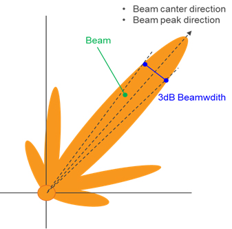
Fig. 1 — Beamforming Terms
The 5G 3rd Generation Partnership Project (3GPP) NR specification [2] has defined four frequency operating bands (Table 1), all of which are time division duplex (TDD). TDD is beneficial to beamforming because of the uplink (UL) and downlink (DL) channel reciprocity. The network equipment can use the UL channel to ascertain the DL channel characteristics, and then chose the optimum beamforming for the DL signal to the UE.
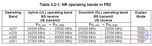
Table 1: Table 5.2-1 of the 3GPP NR Specification [2]
Fig. 2 shows a user equipment (UE) device (e.g., smartphone) with two built-in 5G mmWave modules, each containing a 1x4 patch antenna array and four dipole antennas. For the following discussion, we will consider either the module or the final product as the device under test (DUT). For the example shown, each patch antenna element can have a vertical (V) or horizontal (H) polarization radiation pattern, which transmits or receives electromagnetic waves in either the vertical or horizontal direction.
Beamforming tests of DUTs — such as smartphones, tablets, mobile hot spots, fixed wireless access (FWA) terminals, etc. —usually are performed in a controlled environment, inside an over-the-air (OTA) chamber [3]. Understanding OTA link budget calculations [4] is a critical prerequisite before venturing into beamforming test.
When the antenna module is inside the final product (e.g., the smartphone), the antenna radiation pattern can be altered slightly due to the interaction with the final product enclosure materials and other surrounding components. Thus, the antenna performance, including its beamforming characteristics, needs to be tested using an appropriate OTA chamber of size, architecture, and shielding performance that ensures accurate antenna radiation pattern measurements.
Beamforming testing can be subdivided into two broad categories: beamforming characterization and beamforming verification.
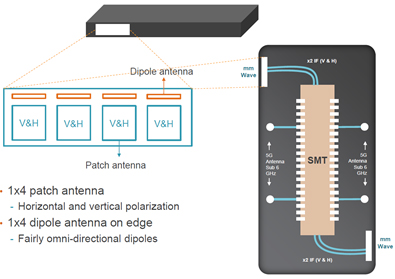
Fig. 2 — User Equipment Device with mmWave Antennas
Beamforming Characterization
Beamforming characterization aims to find the proper phase angle and gain value for each antenna element in order to achieve the desired pattern and direction for the specific DUT design in either its module or final product form. Thus, a beamforming “codebook” needs to be generated that contains the phase angle and gain for each antenna array required to generate a beam in a specific spatial range direction.
Beamforming characterization can be performed using either a CATR or DFF chamber [3], depending on the size of the DUT and its antenna array aperture [4]. The main requirements are that the geometric center of the DUT is placed at the center of the test zone and that the DUT is entirely enclosed in the “quiet zone.” Beamforming codebooks are then characterized and optimized, taking into account each specific antenna design (e.g., dipole, patch antenna arrays, etc.) and the end product system characteristics (enclosure material, antenna locations, etc.). And, since the OTA chamber used for this example comes equipped with a DUT positioner mechanism (a common feature on many OTA test chambers), the DUT can be rotated at various angles while the beam is continuously steered towards the zenith test antenna inside the OTA chamber.
Beamforming characterization can be performed with both VNA and VSA test equipment. However, VNA test equipment has some limitations:
- It requires a “breakout board” to route the IF signals from the VNA to the millimeter wave module. This represents a design and test inconvenience as this board, and accompanying test fixtures, need to be designed.
- Two ports are required: one for the “reference” IF signal and one for the RF measured signal.
- A final product cannot be tested with the VNA as there is no way to access the internal interconnections to the millimeter wave module.
A better approach for beamforming characterization is using a VSA, whose beamforming characterization advantages include:
- Both the module and the final product can be characterized, as there is no need to access the internal millimeter wave signal's interconnections.
- No need for a breakout board and related test fixtures.
- Only one port is required (versus two ports with a VNA) for measuring the OTA millimeter wave signal.
- A VSA offers significant savings on capital investment, as only one piece of equipment is needed for both beamforming characterization and beamforming verification.
In order to achieve VSA testing benefits, “DUT assist” is needed, since the “reference” IF signal now is generated directly from the internal 5G modem (rather than from a VNA). The DUT’s internal 5G modem sets the respective phase and gain for each of the antenna array elements (Fig. 2) and the resulting beam’s signal characteristics are measured and analyzed using the VSA equipment.
Beamforming Verification
The design verification testing (DVT) stage usually requires that a larger sample of DUTs are tested to confirm that the DUT’s beamforming is performing as expected. To achieve this, a subset of the beamforming codebook can be used for “corner case” testing.
Beamforming verification usually is performed using a direct far field [3] (DFF) OTA chamber. Such a setup is very simple and can be used for both module and UE final products.
During beamforming verification, it is the DUT itself that sets the specific phase and gain for each antenna element required to generate a beam in a certain direction (again, using a subset of the beamforming codebook). Thus, only one port is required in the VSA equipment. And, as explained earlier, since the OTA chamber has a DUT positioner mechanism built-in, the DUT can be rotated at various angles while the beam is continuously steered towards the zenith test antenna inside the OTA chamber.
Since a VSA is required for beamforming verification anyway, the test engineer can save significant capital expenditures by using a VSA for both beamforming characterization and beamforming verification, as explained earlier.
Conclusions
Beamforming increases network capacity, increases coverage due to high gain beams, and saves power, as the antenna elements not contributing to the main beam can be turned off. Beamforming codebooks are characterized at the “beamforming characterization” stage and fine-tuned for optimal performance. Beamforming characterization with VSA is much simpler and economical than with a VNA.
About The Authors
Jeorge S. Hurtarte, Ph.D, is Product Marketing Manager at LitePoint Corporation. Prior to joining LitePoint, Dr. Hurtarte held various technical and management positions at Teradyne, TranSwitch, and Rockwell Semiconductors. He holds Ph.D. and B.S. degrees in electrical engineering, an M.S. in telecommunications, and an M.B.A. Dr. Hurtarte has served on the Advisory Board of Directors of the Global Semiconductor Alliance, TUV Rheinland of North America, and the NSF’s Wireless Internet Center for Advanced RF Technology. He is the secretary of the IEEE 802.11ay task group. He is also the lead co-author of the book Understanding Fabless IC Technology.
Vito Liao (Liao, Mingkun) is applications engineer at LitePoint Corporation, where he is responsible for wireless RFFE testing and 5G testing. Vito has many years of experience in cellular chipset physical layer and RFFE driver in 2G, WCDMA, TDSCDMA, LTE technologies.
References
- Simple tutorial on phase array antennas: https://www.youtube.com/watch?v=vtPPAnvJS6c
- 3GPP TS 38.101-2, 3rd Generation Partnership Project; Technical Specification Group Radio Access Network; NR; User Equipment (UE) radio transmission and reception; Part 2: Range 2 Standalone (Release 15)
- Over-the-Air Testing for 5G mmWave Devices: DFF or CATR? Jeorge Hurtarte and Middle Wen, LitePoint. Microwaves and RF Magazine, February 13, 2019
- Link-budget calculations: Needed for 5G OTA testing. Jeorge Hurtarte, LitePoint, EDN Magazine, January 22, 2019