Tuning The Matching Network Of A 2.4 GHz Radio
By Nordic Semiconductor ASA
Preface
This article describes how to tune the matching network of the nRF24xx series radios for optimum performance. The nRF24L01 is used as an example, but the method shown is applicable for all Nordic 2.4GHz radios. A spectrum analyzer is needed to monitor the output signal and measure the performance while the components in the matching network are changed. This article does not cover antenna tuning.
How It Works
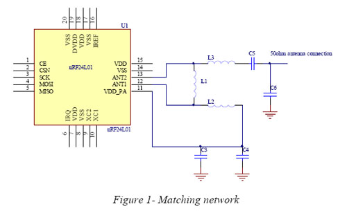
The antenna connection for the radio chip is differential. The impedance is different from 50 ohm. The components between the radio and the antenna are called the matching network and consist of the components shown in Figure 1.
The matching network has 4 main tasks:
- Transform the balanced output of the radio to an unbalanced connection to the antenna (balun).
- Transform the output impedance of the radio to a 50 ohm antenna.
- Suppress harmonics to a level below the regulations level in TX mode.
- Suppress the LO leakage in RX mode.

The balun-function is done by the 180° degrees phase shift in L1. This causes the signals from the two ANT pins, 180° out of phase, to be added in the point between L1 and L3.
Click Here To Download:
•White Paper: Tuning The Matching Network Of A 2.4 GHz Radio
