
RF Voltage Limitations Of A Multi-Layer Ceramic Capacitor In High-Current Applications
By Ed Schoepke, AFM Microelectronics
When putting high RF currents through a multi-layer ceramic capacitor (MLCC), the heating of the MLCC is just one important factor in the limitation of that current. Also important is the voltage that appears across the capacitor relative to the rating of the part. The reactive voltage developed can be much larger than the supplied voltage if the reactance is large, such as at the lower RF frequencies, or when the capacitance value is small. If this voltage is greater than the rated voltage of the part, a catastrophic failure of the part can occur.
In some cases, the catastrophic failure could result in a short circuit, which will damage surrounding circuitry. Additionally, using highly conductive materials in the construction of the capacitor will keep the I2R losses to a minimum, allowing the designer to more easily keep the heat limitation within the MLCC’s specification. The equivalent series resistance (ESR) of the part, which is the R component in this loss, primarily comes from two sources, which will be discussed later in the article.
Example
Using easy-to-manipulate values, let’s compare putting 1 ampere at 150 MHz though a 10 pF capacitor to putting the same current through a 1 pF capacitor.
The reactive impedance of the 10 pF capacitor at 150MHz is: Xc= 1/[2pi(150E6)(10E-12)]= 106.1 ohms
The reactive impedance of the 1 pF capacitor at 150 MHz is: Xc= 1/[2pi(150E6)(1E-12)]= 1061.0 ohms
- Putting 1A of 150 MHz current through the 10 pF capacitor will create a reactive voltage across it of:
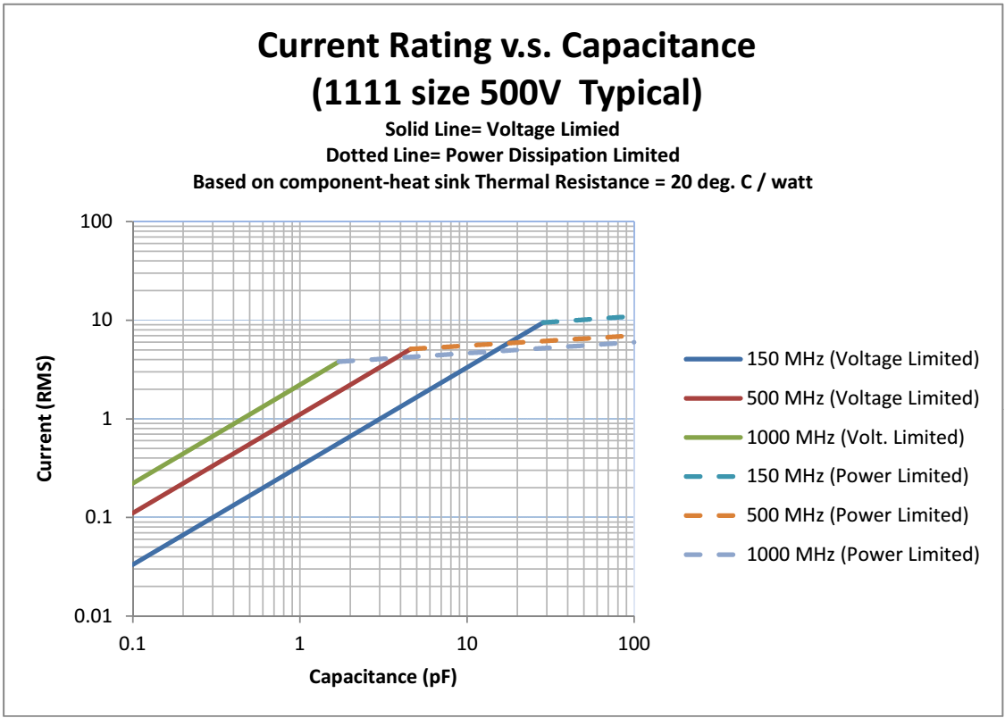
1A * 106.1 ohms * 1.414 = 150 Vrms. This is fine, since the rating of our capacitor is 500V. Note that this is inside the 150MHz curve in Figure A.
- Putting 1A of 150MHz current through the 1 pF capacitor will create a reactive voltage across it of:
1A * 1061.0 ohms * 1.414 = 1500.2 Vrms. The capacitor would then fail although it is far from over-heating due to its power limitations, but the voltage created across it would be well over the 500V rating of the part. Note that this is outside the 150 MHz curve in Figure A.
Looking at Figure A above, the solid lines represent the voltage limited sections of the plot for this 500V rated capacitor. The dotted lines represent the power (heating) section of the plot for this 1111 size capacitor. Do note that the power-limited section is based upon the size of the part, the internal construction of the part, and the component-to-heat sink thermal resistance. The figure assumes a 20 degree C / watt component-to-heat sink thermal resistance, which is a typical value encountered in actual testing situations.
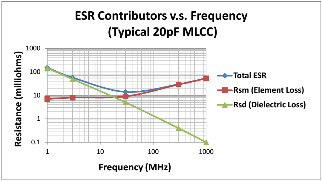
If the internal construction of the capacitor is made of superior conducting material — such as 100 percent silver (no palladium) — and the terminations are made of superior conducting material (such as platinum-silver; again, with no palladium and no nickel), the ESR contribution from the elements will be as small as possible when the skin effect gets very severe over 1000 MHz. The ESR contribution due to the elements starts to predominate above 30 MHz and is essentially the total contributing factor above 1000 MHz.
Figure B below depicts a typical representation of how the ESR contribution from the dielectric losses is greatest at the lower frequencies. But, at higher frequencies, the ESR contribution is almost completely attributable to electrode losses, which climb predictably due to the skin effect. The ESR numbers reported in Figure B are for a standard MLCC.
The Rsm absolute numbers will be lower for 100 percent silver parts. As an example of a resulting benefit in a coupling application, lower loss means more output power, and the lack of Nickel barrier in the termination means fewer problems with hot-spots when high RF currents are passed through the MLCC. These factors will raise the power-limited dotted traces shown in Figure A.
During circuitry design, the voltage limitation of the capacitor needs to be examined, and especially when low capacitance values and lower RF frequencies are used. Using capacitors with low loss characteristics at RF frequencies is also a key to an efficient design.
About The Author
Ed Schoepke is technical sales manager for AFM Microelectronics, a manufacturer of various kinds of MLCCs, including high frequency, high-Q, high-temperature, and high current types.