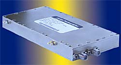
New High Frequency Clock Generator for SONET Systems Available from Elcom

 Rockleigh, NJ -- Elcom Technologies has released a High Frequency Clock Generator for SONET Systems.
This extremely low jitter 21.4 GHz clock generator is a phase locked source having high power differential sine wave outputs. The output power level is +25 dBm per each line of the differential output. This device is intended for timing 150 - 200 MHz applications in 40 GBs SONET systems. The unit operates from a complementary PECL external reference source such as a crystal oscillator. Phase noise of the 21 GHz output is <-105 dBc/Hz at 100 KHz from the carrier, and non-harmonic spurious are <-80 dBc.
Three control functions are included on this clock generator:
- Power level control of the 21 GHz sinusoidal output complementary pair provides a 15 dB adjust range of output power with a 0 to +5 volt externally applied DC control signal
- A phase modulator with +/-150 degree range and modulation bandwidth in excess of 100 KHz
- An I-Q phase shifter which allows continuous phase adjustment over an infinite range of phase
The module has an internal power detector, which provides a DC output signal that varies monotonically with the 21 GHz output power level, and the system includes a phase lock detect alarm output.
Auxiliary low frequency Reference Clock Outputs are optional.
SPECIFICATIONS
Input Clock
- Frequency range: 150 - 200 MHz
Input Clock Signal Format: AC coupled complementary PECL
Connector: Male pins .030" diameter extending from bottom face of unit, intended to mate with printed circuit board sockets plus third pin for ground
Main Output, 20 - 22 GHz: F0+ 128 XFclock
- Output Format: Two Sinusoidal signal, differential output pair, 50 ohm impedance each output
Connector: Female SMA pair
Maximum Output Power: +25 dBm, Minimum per line
Matching of complementary output pair: Amplitude: ±0.5 dB max, Phase: 180 deg ±10 deg, max
Output Power Control Range: 15 dB, Minimum, controlled by an externally applied 0 V to +5 V DC analog input signal
Output Return Loss: 10 dB, Minimum
Phase Adjust, Analog Phase Shifter:
- Range: 0 degrees to +300 degrees min/+400 degrees maximum under control of a 0 V to +5 V DC analog input signal.
Modulation Bandwidth: 50 KHz, Minimum
I-Q Modulator Phase Adjust: Continuous, monotonic phase adjust over an infinite range under control of an I-Q input pair driven be external current sources. Input current range for these inputs is -5 mA to +5 mA. Input currents are to be applied according to a given sine/cosine type of analytic function.
SSB Phase Noise: -103 dBc/Hz max at 100 KHz offset from the 21.4 GHz carrier
Reference Clock Outputs
- Frequencies: Fclock X 4, Fclock X 16
Format: AC coupled differential LVPECL pairs, two pairs per frequency
Connector: Male pins .030" diameter extending from bottom face of unit, intended to mate with printed circuit board sockets plus additional pins for ground
