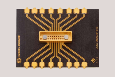
MXPM PCB Socket Assembly

Discover the critical assembly procedures for the HUBER+SUHNER MXPM PCB Socket, a high-performance, semi-SMT RF connector system. Achieving the full rated electrical performance requires strict adherence to specialized manufacturing specifications, which HUBER+SUHNER supports with engineering assistance for design and footprint optimization.
The document emphasizes the importance of a suitable, matched impedance footprint for RF signals, noting that its design is highly dependent on PCB characteristics, such as the dielectric constant and layer thickness, often necessitating electromagnetic 3D-field simulation. Recommended practices include the use of filled vias for signal paths and specifying impedance-controlled boards from experienced manufacturers.
Material recommendations focus on gold plating for soldering, with a cautionary note regarding the potential for thick gold layers to cause brittle solder joints. For component placement, the MXPM sockets are compatible with standard pick-and-place systems and are supplied in tape and reel format, certified for Unlimited Floor Life (Level 1).
Crucially, soldering must be performed using industrial reflow equipment or a reliable rework station; soldering irons or hot air pencils are inappropriate. The guide pins support pin-in-paste technology, requiring a Type 3 solder grain size and a recommended paste thickness of 150 & µm. Specific guidelines are provided for pin protrusion (maximum 1.5mm) and visual inspection procedures for the pin-in-paste technique.
Get unlimited access to:
Enter your credentials below to log in. Not yet a member of RF Globalnet? Subscribe today.
