
Key Test Considerations For A Quality 5G Wireless User Experience

By Adam Smith, LitePoint
In part 1 of this series, we explored the variety of wireless technologies that make up 5G — a family of technologies optimized for a variety of use cases. Technologies considered in the 5G wireless family include high-bandwidth millimeter wave wireless, such as the 5G New Radio and WiGig, and the continually evolving LTE cellular and Wi-Fi (802.11ax) standards. Additionally, lower bandwidth, sub-GHz protocols, such as LoRa and SigFox, round out use cases in industrial IoT applications.
While all these technologies are considered in the 5G taxonomy, the testing requirements for higher bandwidth wireless LAN (WLAN) and cellular technologies are different from those of the lower-speed IoT technologies. This article will focus on the testing challenges facing these higher-bandwidth technologies.
Millimeter Wave / 802.11ad / 5G New Radio
Millimeter wave (mmWave) radio technologies take advantage of 20 GHz of underutilized spectrum in the 28 GHz, 39 GHz, and 60 GHz bands for a range of new, Gigabit-plus throughput wireless services. Among the 5G technologies leveraging mmWave is WiGig (802.11ad), which is designed to offer a maximum of 7 Gbps of throughput and operates in the 57 GHz to 66 GHz frequency range. Also, mmWave frequencies currently are undergoing trials for future 5G New Radio (NR) cellular technology.
Like other next-generation, high-bandwidth wireless technologies, mmWave leverages massive multiple-in multiple-out (MIMO) antenna configurations and adaptive beamforming to focus significant amounts of RF energy onto a receiver for high-bandwidth services. Massive MIMO — loosely defined as anything more than 16 antennas, and potentially up to hundreds of antennas — provides much higher spectrum efficiency thanks to spatial reuse, as well as higher capacity, with a reduction in latency and jitter. These performance parameters make mmWave service appropriate for emerging applications like autonomous vehicle control and industrial automation.
mmWave Testing Challenges
mmWave systems can no longer be tested in a controlled 50–ohm cabled environment, where the tester is physically connected to the device under test (DUT). This testing environment was the best practice for testing wireless systems operating below 6 GHz. While not capturing real-world conditions, these cabled testing environments did allow for more repeatable results. For mmWave systems, over-the-air (OTA) test methodologies are required for more practical testing, given the frequencies involved.
OTA systems are optimized to test beam forming, which leverages multiple antennas to direct a single RF beam to a receiver. OTA testers can efficiently test that each antenna’s phase shifter is working properly, validating that the antenna array can point the energy to the end device.
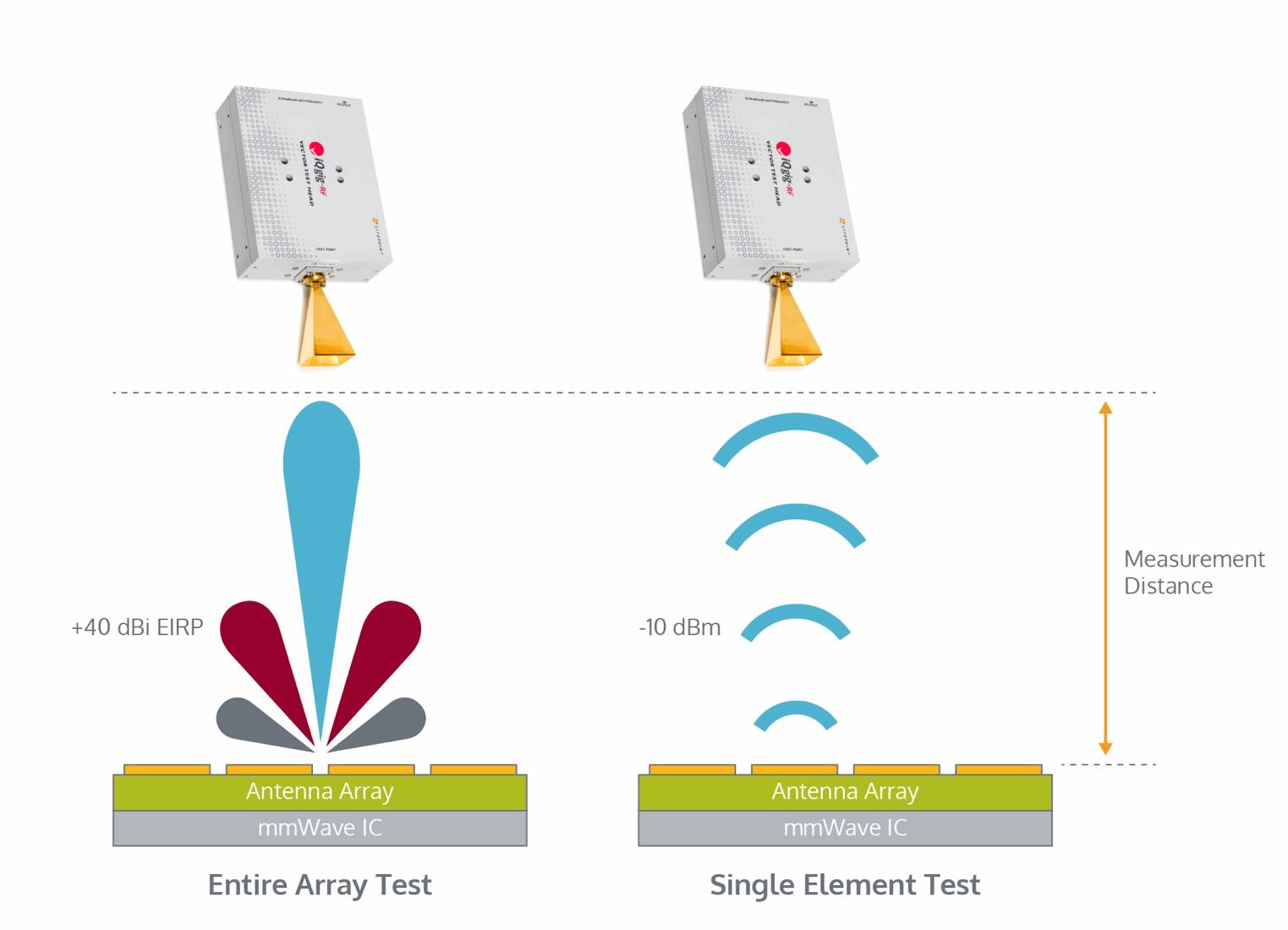
There also is a need to test the antenna integrity both separately and as an array. Due to the significant amount of path loss at mmWave frequencies, massive MIMO leverages the gain of all the antennas acting together. But, within that array, an individual antenna could have performance issues. The tester must stress both the array and each individual antenna. This requires a tester with a high dynamic range to capture the power range between the low of the individual antenna and the high of the antenna array.
Recognizing that in many systems, mmWave will coexist with 2G, 3G, and 4G radio access technologies (RATs), a last challenge for mmWave testing is to evaluate the system control plane that must hand off data between RATs. The tester needs to measure the timing of these handoffs to ensure they fall within latency boundaries to not impact voice or data transmissions. Automating this process is critical, as there are many co-existence and hand-off permutations, so this testing needs to be done rapidly with high repeatability.
Next-Generation 4G/LTE
Next-generation 4G/LTE wireless technologies still will be a key part of the 5G network, delivering higher bandwidth in the short-term and augmenting 5G NR networks for many years to come. In fact, many consider LTE Advanced Pro, which is designed to deliver Gigabit+ throughput, to be within the 5G taxonomy.
A critical feature for 4G/LTE test equipment is test sequence automation, which lets the tester trigger the automated test sequences that chipset manufacturers build into their chips. The ability to execute these test sequences minimizes test setups and back-and-forth programming of some of the standard chip functionality tests. These sequences are becoming more thorough, adding new tests with very small step sizes — sometimes less than 1 millisecond per step. This requires the tester to have very fast settling times for its signal generators and analyzers, so that they can reset and be ready for a new test in less than 100 microseconds.
Because of increasingly complex board designs in today’s mobile devices, intersystem noise can be a significant factor that needs to be tested. Intersystem noise is created from electrical signal radiation that interferes with data signals due to the densely packed traces. This interference can desense the Wi-Fi or LTE signal, impacting wireless performance when the device is at the edge of its signal range.
Testing for signal desensing involves turning on the LTE signal and then measuring signal strength while other phone systems are turned on and off; and then repeating the process for the Wi-Fi, Bluetooth, and other radios. This testing requires an OTA connection for accurate, real-world measurement of the signal strength, as well as extensive automation to facilitate the large series of tests.
There also are some testing challenges brought on by the use of carrier aggregation (CA) in LTE Advanced Pro for higher data rates. CA combines multiple channels of LTE spectrum in a single mobile device. This can be done with up to five component carriers, depending on the desired data rate. Ideally, the carriers are adjacent or close together, but that’s not often found due to the very fragmented LTE RF spectrum. To compensate, inter-band carrier aggregation was created to combine channels from completely different LTE bands — some with over 1 GHz in spacing. This situation challenges the aggregation function in the RF front end, so multiple radios are being built into the mobile device to simplify the architecture. From the test perspective, each of the radios needs to be calibrated and tested, driving up test times.
5G For The WLAN - 802.11ax
Both in terms of bandwidth and the number of users that can connect to the AP at any one time, 802.11ax promises much more wireless LAN capacity. A key change to the Wi-Fi standard to achieve these objectives is the adoption of orthogonal frequency division multiple access (OFDMA), the modulation techniques used in LTE/4G networks.
In OFDMA systems, each access point allocates time and frequency to attached devices, expanding the capacity from previously used WLAN modulation schemes, which allocate the entire bandwidth of a connection to a single user for the duration of the transmission. An OFDMA AP can dynamically control the frequency, giving more to a user watching a streaming video and less to one sending email. Test systems must account for timing synchronization, frequency alignment, and response time characteristics to ensure APs perform correctly.
Also, 802.11ax features power control, which provides fair access to the network for both high-power devices (those nearest to the base station) and low-power devices (those far from the AP). Without power control, high-power devices could desensitize the system, effectively reducing the channel capacity. APs measure the power of connected stations (STAs) via a received signal strength indicator, and can signal STAs to reduce or increase their power levels to ensure fair access. This capability is refined by the 802.11.ax standard, which designates device classes based on power control accuracy. Class A devices offer +/-3dB of power control, which means more STAs can connect to an AP than a class B STA, which features +/- 9dB power control.
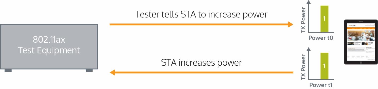
The test system must emulate the real-time power control responses of an AP. In essence, the tester acts like an AP and sends power level information (coded in a packet header), and then measures the response from the STA DUT. The tester evaluates the power level and sends out a command to increase or decrease the power level, and measures the accuracy of the response. The test also should determine the settling time it takes for the DUT’s power level to reset due to power amplifier response times or power control loops. To achieve the real-time performance and low latency (~200 ms) for power control testing, it’s critical that test systems deliver this functionality via hardware.
802.11ax Timing Issues
Multiple users simultaneously using an 802.11ax AP can increase intercarrier and intersymbol interference, which can reduce overall system capacity. To minimize interference, the 802.11ax standard features a timing requirement that all STAs must transmit within 400 ns of each other to minimize interference. The AP coordinates this synchronization using a trigger frame that is sent to each STA, which provides the timing requirements for their transmissions, as well as information on the frequency sub carriers they can use.
To test for this, an 802.11ax tester must emulate the AP and generate the trigger frames. The tester measures the time from when the trigger frame packet left the tester to when the DUT packet was received. This time needs to be the short interframe space (SIFS) time +/- 400 ns. Another timing test helps to calculate the carrier frequency offset — the frequency error in the STA after it has been synchronized — to ensure it meets the standard of 350Hz. Like the timing error test, the tester sends the DUT a trigger frame, which is decoded by the DUT and used to align its clock before the device responds by sending a packet back to the tester, which then is used to calculate CFO.
Conclusion
High-speed 5G technologies promise a great foundation for use cases ranging from video streaming to autonomous cars, but these applications will depend on reliable performance from the network technologies. The added complexity of these technologies means the potential for longer test times, which negatively impacts production volumes. This is an age-old dynamic for the wireless industry. Test system manufacturers are responding with more automation and faster systems to minimize the cost of test. With these systems, it’s possible to ensure the maximum performance and quality for 5G users.
Read part 1 of this series here.
About The Author
Adam Smith is the Director of Marketing at LitePoint and a 15-year veteran of the RF industry, with expertise in cellular and connectivity technologies. A member of the LitePoint team since 2012, Adam’s knowledge and experience has been instrumental in driving product strategy for LitePoint test solutions.