
Integration Considerations: Software-Defined Antenna Technology
By Jeff Shamblin, Taoglas

The number of devices connected to cellular networks continues to increase, with these devices encompassing consumer, industrial, and enterprise devices. As the networks become more congested and saturated, system-level improvements are needed to accommodate ever-increasing data rates and reliability requirements.
A software-defined antenna system, or “smart antenna” approach, will provide several dBs gain of system-level improvement compared to client devices that incorporate traditional passive antennas. Proper integration of a software-defined antenna is key to obtaining maximum benefit for both 4G and 5G communication systems where MIMO antenna systems are required.
A software-defined antenna system provides an antenna that is reconfigurable. The antenna can be dynamically optimized to compensate for changes in the radio protocol, propagation channel, or other variations in the operating environment. They are particularly useful when cellular and Wi-Fi systems are used. Compared to the commonly used passive antenna, a software-defined antenna can provide a beam-steering function, which will direct more gain at the device or client side of the communication link. Additionally, the directive radiation pattern generated for beam steering provides interference mitigation for interferers that fall outside the antenna system's main beam.
This improved gain at the intended node, along with interference suppression, allows optimization for both signal and interference, which substantially improves signal-to-interference-plus-noise ratio (SINR). We use the term “system” to describe the software-defined antenna because this is, indeed, a system approach — where an algorithm, radio system metrics, and tunable components all need to come together to implement this optimized technique.
Component Innovation And Availability
Software-defined antennas have become more feasible in the last decade due to innovations on two fronts: RF tuning components and RF modem chipset design. A wide variety of RF tuning components — and manufacturing techniques to support these components — has matured over the last eight to ten years, with the component list comprising RF switches, RF tunable capacitors, MEMS switches and tunable capacitors, BST tunable capacitors, and PIN diodes.
On the modem chipset front for 4G and Wi-Fi modems, the metrics available for “real-time” dynamic optimization are available at moderate to low latency, with these metrics typically including SINR and Channel Quality Indicator (CQI). Metrics like these can be used to make decisions as to the most optimal antenna system tuning state.
Timing is critical
To optimize a software-defined antenna for a beam-steering application, timing is a key metric for success. Here’s a timing snapshot:
- The radiated EM wave from the antenna travels one meter in 3 nsec (one-billionth of a second)
- A typical tuning component used to configure the software-defined antenna can switch in 1 µsec (one-millionth of a second)
- Metrics from the baseband radio chipset can be updated in a few hundred µsecs
- The algorithm “decision-making process” may require 1 to 50 msec (one-thousandth of a second)
The goal is to sample multiple antenna beam states using 1 µsec switching, collect and survey baseband metrics (hundreds of µsecs), and optimize for transmission and reception over the communication link in msecs.
Looking at timing from another perspective, the propagational channel is fluctuating due to the mobility of the client device, and these fluctuations in the transmitted or received signal are frequency dependent, with fluctuations occurring more rapidly at higher frequencies. The goal is to optimize the software-defined antenna as quickly as possible by converging to the optimal beam state. The factors driving this timeline to optimization are latency of baseband metrics, algorithm efficiency, and frequency of operation.
Fig. 1 highlights the concept of nanosecond through millisecond functions being accommodated during the software-defined antenna optimization process implemented by an algorithm.
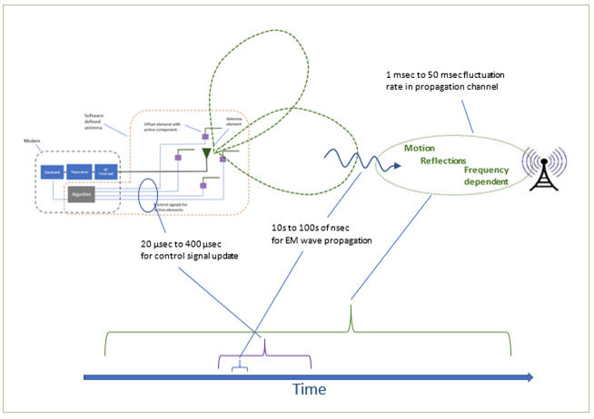
Fig. 1 — Timing aspects of software-defined antennas control
Antenna + Radio together = Best performance
Wireless consumer product designers are continually under pressure to design smaller devices while increasing functionality. A cellular router, which can contain software-defined antennas, is no exception. Besides size reduction, there are other strong motivations to integrate the radio modem with the software-defined antenna system.
By integrating the radio modem with software-defined antennas, the RF cable loss can be minimized, along with weight and cost. Additionally, the digital control cable used to provide control signals for the tunable components in the antenna system can be reduced in length for cost and weight considerations. With the software-defined antenna being an electronically tunable antenna system, there will be a circuit board associated with the antenna; by integrating the radio modem and software-defined antenna system into a single package, the circuit boards can be combined into a single board, or a stacked PCB approach can be taken to minimize the size of the device. A single plastic enclosure can complete the product. An algorithm needs to be customized to synchronize and optimize the software-defined antenna with a specific radio modem, and the algorithm can be housed in a processor in the modem or reside with the software-defined antenna.
Bigger Is Better
Considering an LTE requirement for implementing a software-defined antenna in a client device, the antenna design will need to accommodate low frequency bands — such as Bands 12, 13, 17, and 5 — as well as high frequency bands (1, 2, 3, and 4, for example). The low-frequency band requirements will drive antenna size or overall volume. If the goal is to achieve a 3 dB improvement in antenna gain, the area for a planar antenna or volume for a 3D antenna will typically need to double. If there is not available space for this size increase, the decision can be made to provide a directive beam-steering function at the higher frequency bands only while maintaining a passive or fixed radiation pattern at the low frequency bands.
Alternately, the decision can be made to provide 3+ dB of gain improvement at the high frequency bands while maintaining 1 to 2 dB of gain improvement from a beam-steering function at the low frequencies. This trade-off in beam-steering performance can be made to balance antenna system performance with size constraints. If 6 dB of antenna system performance is required, the passive antenna will need to quadruple in area or volume, with the trend being a doubling of area or volume for each 3 dB of improvement.
An Example
To drive home the concepts discussed here, let’s look at an example of how an integrated radio modem/software-defined radio is configured. A subsystem approach can be taken to design a radio modem board and a separate software-defined antenna board.
For a 2x2 MIMO system application for cellular, three cables can be used to connect between the subsystems, two RF and one digital control. With best practice in PCB design across the pair of boards, a pair of multi-pin connectors can be implemented to eliminate the digital control cable. The software-defined antenna requires an algorithm for beam state optimization, so there is flexibility as to which processor is used, and within which subsystem to place the processor and algorithm.
A standard enclosure can be used and provides a lower-cost solution, compared to separate enclosures on two discrete subsystems. Integrating the radio modem and software-defined antenna together will lead to cost and weight savings, along with reduced coaxial cable losses, which will result in better transmit and receive performance (Fig. 2).
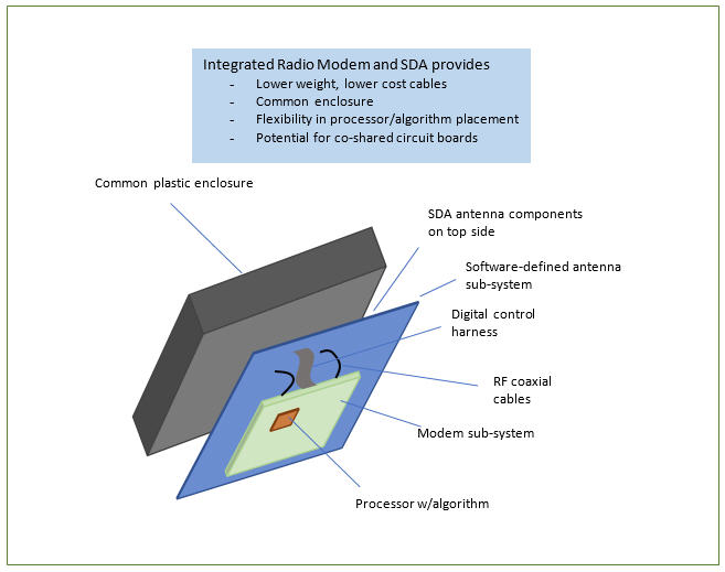
Fig. 2 — Integrated radio modem and software-defined antenna system
Conclusion
As software-defined antenna systems gain traction in commercial cellular and Wi-Fi applications, it will be important to properly integrate the antenna system and radio modem to receive the full benefit in throughput and communication link reliability. Cost, weight, and space savings can be gained to complement the improvements in system-level performance. Proper integration of a software-defined antenna is key to obtaining maximum benefit for both 4G and 5G systems where MIMO antenna systems are required.
About The Author
Jeff Shamblin is vice president of engineering at Taoglas, a provider of IoT and automotive antenna and RF solutions. Shamblin holds 81 issued patents related to antenna technology and communication systems. Before Taoglas, Shamblin spent 12 years in the roles of CTO and chief scientist at Ethertronics, and was responsible for R&D projects related to active antenna techniques directed towards commercial communication systems. He also spent five years in engineering roles at two RFID start-ups, SCS Corp. and Claridy Solutions, and 22 years working as a senior antenna engineer in aerospace for Lockheed Martin and Northrop, designing antenna systems for aircraft, missile, and ground station applications.