
How New DAC Technologies Are Changing Radar & EW Signal Generation
New high-speed digital-to-analog converters (DAC) embody signal processing, modulation, and generation functionalities, and are capable of directly synthesizing complex signals at microwave frequencies.
By Christopher Skach and Sahand Noorizadeh, Tektronix
A wide number of application areas in radar and electronic warfare (EW) system, sub-system, assembly, and component design work have complex signal generation needs, which often cannot be met with commercial off-the-shelf (COTS) signal generation solutions. This has led to the use of custom-designed solutions for analog signal generation that are expensive and inflexible compared to COTS alternatives, such as arbitrary waveform generators (AWGs) that offer direct synthesis of signals of interest.
Engineers designing systems that detect and protect from electronic threats require complete capture and playback solutions that will allow them to stimulate radar receivers for design, troubleshooting, or compliance testing. Signal generators also are needed for automated testing of radar/EW systems and components. To thoroughly test a radar or EW device, test signals must accurately recreate the RF/microwave environment the device will face, including noise and interference, as well as any modulations used by the device. For measurements that involve occupied spectrum, a significant number of test sources may be needed to simulate the various RF and microwave signals that could be coming from other radars, Wi-Fi routers, or smartphones within a given spectrum.
As the complexity of radar/EW signals has increased, COTS signal generation solutions have struggled to meet agility, bandwidth, signal fidelity, scalability, and memory requirements. To address these challenges, a new class of high-speed digital-to-analog converters (DAC) is emerging that embody signal processing, modulation, and generation functionalities, and are capable of directly synthesizing complex signals at microwave frequencies.
Designing a DAC with both a high number of bits and a high sample rate with good dynamic range has proven to be a difficult undertaking. While this has been a hindrance in the past, DAC technology is now far enough along that it is possible to directly generate high-frequency signals, with high fidelity, directly out of the DACs. There remain some limitations, and an upconverter or mixer may still be needed at times, but modern DACs now can cover radar/EW signal requirements directly.
Driven in part by demand for less expensive and smaller devices for telecommunication and military systems, some DACs are starting to incorporate signal processing blocks and modulation, in addition to signal generation functionalities. The most useful of these digital signal processing blocks include complex (or I-Q) modulation, numerically controlled oscillators (NCOs), and conditioning functionalities, such as FIR filters and digital interpolation. Such all-in-one packages enable direct generation of complex RF signals in an efficient, compact, and, ultimately, more affordable way. This, in turn, is leading to development of new AWGs well-suited for more advanced and complex RF and military and defense applications.
Microwave Signal Generation
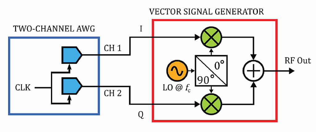
To fully appreciate why these advances in DAC technology are so significant, it’s helpful to look at the challenges of generating complex microwave signals. A common method to generate complex signals is to modulate a carrier signal with frequency generated by a local oscillator (LO) using a vector modulator, essentially a hardware implementation of the following trigonometric identity:
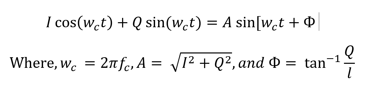
This formula can be conveniently implemented in hardware by noting that sin(wct) = cos(wct + π / 2), which implies that, by shifting the phase of the carrier signal by 90 degrees, the sine and cosine terms on the left side of the above equation can be produced from a single sinusoidal source. The I and Q terms are the in-phase and quadrature baseband signals, respectively, and these terms can set the amplitude and phase of the carrier signal to any arbitrary value, which allows for the implementation of any type of modulation.
High-Speed DACs With Complex Modulators
The latest DACs overcome many of the problems with generating complex microwave signals by integrating more functionality into a single chip. In Fig. 2, a high-speed 16-bit DAC is used in a next-generation AWG featuring a digital complex modulator and multi-rate interpolation.
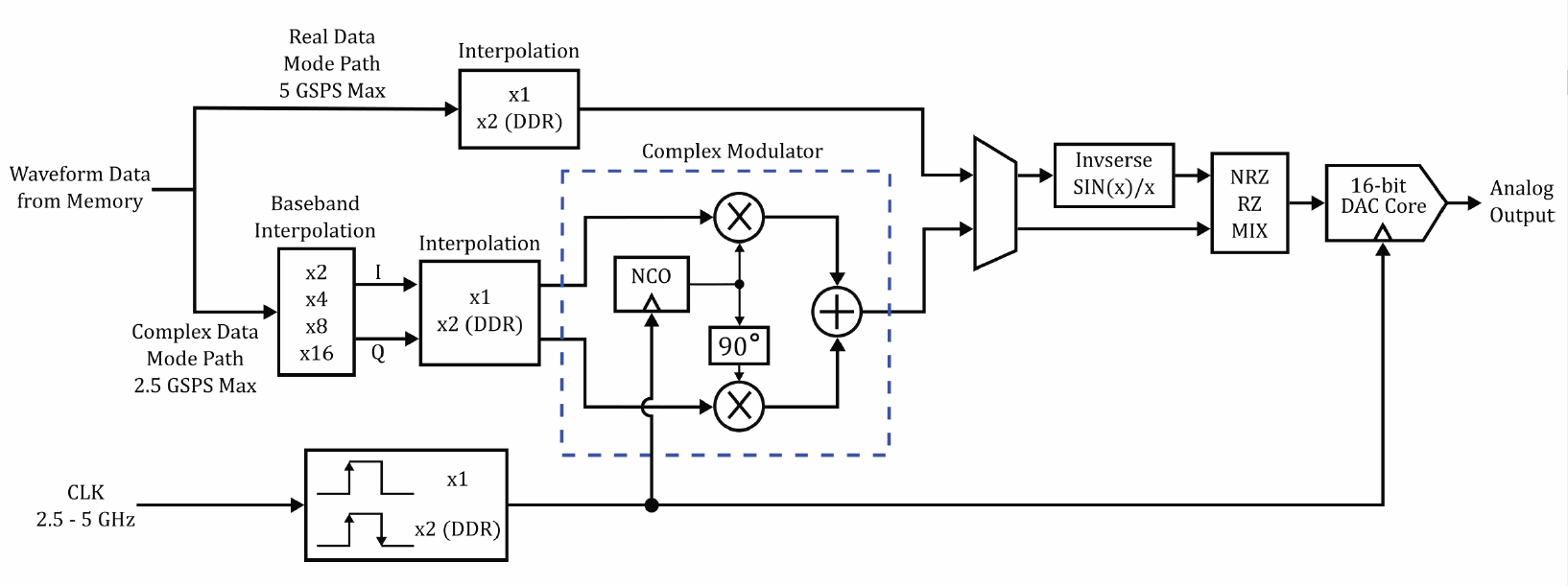
The complex modulator is a digital implementation of a vector signal generator (VSG). The NCO acts as the local oscillator, providing the carrier signal, and the user-defined I and Q baseband signals are digitally streamed into the DAC from an off-chip memory. The output of this modulator is a digital waveform applied to the DAC core. The frequency of the NCO is controlled using a dedicated on-chip register that can be independently programmed, allowing for the carrier frequency to be tuned without recalculating or reloading of the I-Q waveforms.
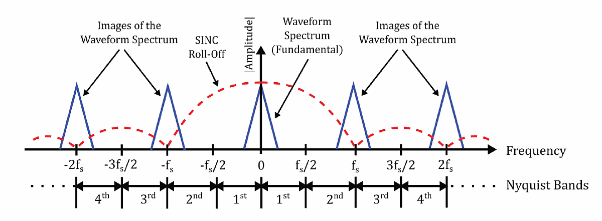
Interpolation in the digital data path is used to generate waveform data, which is supplied to the DAC at lower sample rates to reduce memory requirements. Two independent interpolation blocks are included: a baseband block with selectable factors from 2x to 16x, and a block associated with the double data rate (DDR) clocking feature. When DDR is off, data is converted only on one of the clock edges, and the interpolation mode is set to x1. When DDR mode is used, data is 2x interpolated and converted on both edges of the clock signal. While in DDR mode, the NCO’s sample rate also doubles, meaning that, at the maximum clock frequency of 5 GHz, the NCO and the DAC core are running at a sample rate of 10 GS/s, and carrier frequencies up to 5 GHz in the first Nyquist band can be synthesized.
With a reconstruction filter at the output of the AWG, analog signals with complex modulation can be directly generated up to nearly 5 GHz. Signals at higher frequencies are also possible using higher order Nyquist bands.
Direct Signal Generation
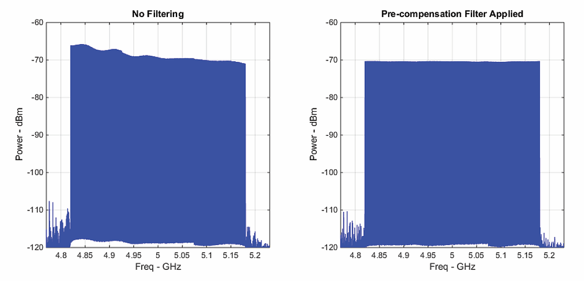
The amplitude and phase distortion due to the composite frequency response of the AWG and the external components can be compensated by applying a FIR filter to the I and Q waveforms in the digital domain. Fig. 5 shows such a filter applied to a multi-tone waveform in the 2nd Nyquist band centered at 5GHz. This waveform was created using the complex modulator with the same AWG setting as was used for the Gaussian pulse.
Superheterodyne Up-conversion
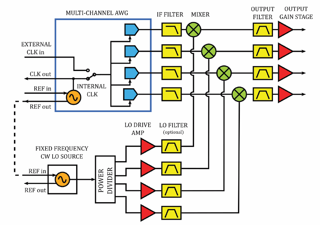
Even with new DACs’ improved performance and lower noise floor, there will be cases where the desired frequency is too high to use the higher-order Nyquist bands effectively and with good dynamic range. In these cases, a superheterodyne up-conversion scheme, using the NCO and an external mixer, is a useful way to extend the output frequency coverage of the AWG.
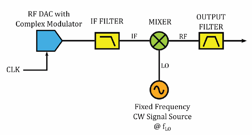
While this is a somewhat more complex set-up than what’s needed for lower frequencies, having a fixed LO offers a significantly lower cost to complex microwave signal generation, compared to the traditional VSGs that use IQ modulators and analog synthesizers as the LO. Additionally, only one AWG channel is needed to generate both the I and Q baseband signals, whereas a VSG requires two AWG channels: one for the I waveform and another for the Q waveforms. Also in contrast to VSG, the LO leakage is out of band from the main signal spectrum and can be filtered out. This is extremely advantageous when very high on-to-off ratio is desired for pulsed signals.
Further, since the modulation is done in the digital domain, the quadrature relationship between the I and Q waveforms over the entire signal bandwidth is preserved, so no calibration for correcting the I-Q imbalance is needed. Distortion due to the frequency response of the analog path can be compensated by applying pre-compensating FIR filters to the I and Q waveforms in the digital domain (Fig. 5).
A New Approach To Signal Generation
Generating the analog signals needed to simulate a complex threat environment has traditionally involved large racks of specialized equipment. That is changing with the availability of DACs that offer a mix of speed and resolution, coupled with a built-in IQ modulator, providing a wide RF output range along with VSG functionality. These DACs, in turn, are enabling the development of AWGs that can directly generate highly detailed radar/EW signals, making modern signal generators a true COTS alternative for many radar/EW test applications.
[Editor’s Note: A Tektronix AWG5200 was used for examples discussed in this article, and was the basis for Fig. 2. This statement is meant only to provide context for the results depicted, and is not intended as an endorsement of the product by this publication.]
About the Authors
 Christopher Skach is an applications engineer for Tektronix’ Source Analyzer Product Line and is based in Beaverton, Ore. He received a BSEE in electronics from Oregon Institute of Technology and has been instrumental in the design and support of signal source, spectrum analyzer and oscilloscope products during his 39-year tenure at Tektronix. Additionally, he is the author of papers on such topics as Method of Implementation (MOI) for standards such as SATA, USB 3.0 and HDMI.
 Sahand Noorizadeh is an RF and microwave design engineer for Tektronix’ Sources and Analyzer Product Line and is based in Beaverton, Ore. He received his BSEE from Georgia Institute of Technology with a focus on RF and analog circuit design, and his MSEE from Portland State University with a research focus on electromagnetics and Fourier optics. In his role as a microwave hardware designer and system architect, he contributes to the development of high performance AWGs and RF signal generator products.