
Eagleware Announces New Capability for Power Amplifier Designers
Load-Pull Based PA Design
Eagleware announces full support of FOCUS Microwaves and Maury Microwave load-pull data files. These files contain power device characterization in the form of power-versus-reflection coefficient. These files are used to design terminations for a desired output power, and are plotted on a Smith Chart in GENESYS, as shown in the figure. Complete with user-selectable contour smoothing and thin-plate spline interpolation.
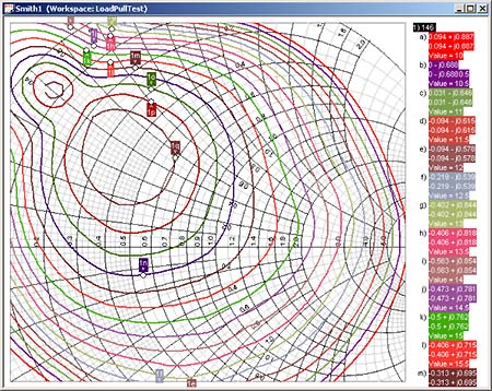
Easily plot load-pull data on a Smith Chart complete with user-defined data markers. You can overlay circuit simulation curves for the most power and flexibility in amplifier design.
Large Signal S-Parameters
New measurements now display large-signal s-parameters measurements. Calculated from node voltages and branch currents, these parameters allow the designer to view the change of circuit characteristics as a function of signal level. For example, you can look at the change in amplifier input impedance as the input level is increased. More advanced parameters, such as large-signal stability, can be calculated using the large signal s-parameters.
Motorola LDMOS Support
The Motorola Electro Thermal (MET) model for RF LDMOS transistors includes full characterization of electro-thermal phenomena including device self–heating impact on performance. This model, designed by Motorola, is tailored for high power RF LDMOS transistors used in wireless base station applications. For distribution authorization, strict adherence to design guidelines is required. Eagleware underwent extensive testing by Motorola to verify convergence and other modeling criteria. A full library of transistor models complete with package parasitics and device parameters is included.
TEST LINK
Support has been added for data acquisition from more than ten analyzers and oscilloscopes in the new version. Engineers can automatically acquire data from measurement equipment with a click of the mouse. The data is automatically stored inside GENESYS to facilitate comparison with simulations and other data.
GENESYS V2002.09 has many additional features aimed at general design:
Antenna Design
Patch antennas are used in an ever-increasing range of wireless applications. The low cost of manufacturing and the small size are ideal for hand-held devices. GENESYS V2002.09 extends the power of antenna electromagnetic simulation to include the display of antenna patterns. Fully integrated into the GENESYS environment, you can see patterns from configurations of metal on multiple levels, even helping you understand unintended trace radiation.
Antenna pattern plots are created for arbitrary topologies using data calculated from EMPOWER, the GENESYS planar electromagnetic simulator. You have the ability to simulate free-space and substrate-embedded antenna designs as well as conventional patch antennas. Antenna pattern plots will display in 3D space by sweeping azimuth and elevation.
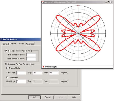
Generate far field patterns from any PCB layout.
The EMPOWER far-field radiation viewer data describes the electric field patterns in the far-zone region radiated from a structure. The far-zone is defined as the region where 2lR/l » 1, where R is the distance from the structure and lambda (l) is the wavelength of the signal exciting the structure. This means that the distance from the antenna is many wavelengths. Far-field radiation patterns are described in a spherical coordinate system, where phi is the angle on the xy plane from the positive x-axis, and theta is the angle from the vertical (positive z) axis.
New Models
The range of accurate models keeps expanding in GENESYS. V2002.09 now includes:
Microstrip
- Arbitrary-angle, optimally mitered bend automatically determines the best miter to minimize return loss due to bend discontinuities. This allows the design of arbitrary microstrip topologies while maintaining proper matching characteristics.
- Asymmetric TEE allows all three branches of the tee to be different widths.
System
- 1-3 to 1-20 way RF Switches allow you to more easily model complicated systems with many branches, including inter-branch isolation effects.
- Frequency Multiplier allows the modeling of high order multipliers, including the multiplication effects on phase noise.
Nonlinear Devices
- Motorola MET model for LDMOS devices. Includes the library of over 60 Motorola device and package models
User defined non-linear modeling using the SPICE-like POLY function with voltage controlled and current controlled current sources
Passives
- Multi-coupled inductors
- Impedance inverter
- Frequency independent complex impedance
GENESYS V2002.09 is now shipping. Prices start at $7,000 US for power amplifier simulation.