
Considerations For Optimal Capacitive Coupling
By Richard Fiore
Director of RF Applications Engineering
American Technical Ceramics Corp.
Capacitors used in coupling and DC blocking applications serve to couple RF energy from one part of a circuit to another and are implemented as series elements. Proper selection of coupling capacitors insures the maximum transfer of RF energy. All capacitors will block DC by definition; however, considerations for satisfying the requirements of a coupling application depend on various frequency-dependent parameters that must be taken into account beforehand.
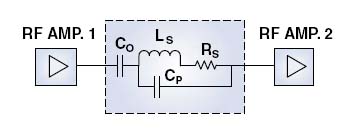
Figure 1: Interstage Coupling Block Diagram
Figure 1 illustrates two RF amplifier stages operating in a 50-ohm network interconnected by coupling capacitor C0. Table 1 outlines several device options for achieving interstage coupling at various wireless frequencies. Electrical parameters such as the series resonant frequency (FSR), parallel resonant frequency (FPR), net impedance, insertion loss, equivalent series resistance (ESR), and Q must be evaluated in order to achieve an optimal coupling solution.
Note: Coupling capacitor C0 in Figure 1 is represented with its equivalent series resistance (ESR) denoted as RS, equivalent series inductance (ESL) denoted as LS and parasitic parallel capacitance CP, associated with the parallel resonant frequency (FPR).
Click here to download the complete article in pdf format.
(Reproduced with permission of Microwave Product Digest, March 2004)