
Coexistence With LTE And The Critical Defense Services: Benchmarking Cooperative Receiver Performance
By Darren McCarthy
The methods described invoke several commercial references and standards to guide performance requirements.
In the age of spectrum sharing and licensing of new communication bands adjacent to defense infrastructure and communication systems, it is necessary to look at the potential impact of commercial systems on the receiver performance of critical systems like Secure Communications (COMSEC) and radars.
While international interoperability recommendations typically focus on the transmitted emission impact of systems,1-4 a new focus on test and verification methodology must consider the impact on receiver performance. This is a critical review due not just to the proliferation of wireless communication bands in the U.S., but also for using defense assets in any expected worldwide forward deployment environment.
Smartphones are accelerating the pace of wireless communications around the world. With base stations from various service providers often co-located on the same tower, coexistence has been a critical part of their design. Not to mention that each phone contains many cellular frequency bands, as well as Wi-Fi, Bluetooth, and GPS. Coexistence is intrinsic to the function of cellular communications systems.
Within the DoD, military electromagnetic compatibility standards — like MIL-STD-464C — have provisions for Inter-system EMC that are primarily concerned with interforce effectors. Emission limits, margins, and environments are given as reference to the levels of the expected transmitters (radio relays, radars, etc.), but guidance on the susceptibility to commercial wireless technology is largely ignored.
As U.S. and NATO forces look to utilize common assets to support global efforts, it is essential to look at some of the critical COMSEC and radars that can be impacted, at the receiver, by commercial services. It is worth stating up front that, while GPS reception is important to situational awareness for assets like the Defense Advanced GPS receivers (DAGR) and Selective Availability Anti-Spoofing Module (SAASM), radars and communications systems also require the GPS reception for critical timing needs.
Denial or disruption to GPS, or inadequate receiver design performance to nearby cellular systems, can influence all systems. For this reason, this article focuses on receiver performance of the GPS receiver, rather than a specific COMSEC radio.
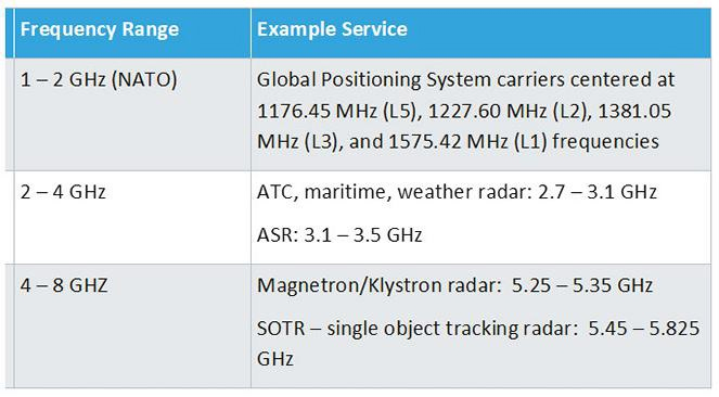
Table 1. Critical frequency bands and civilian/defense services
Table 1 shows some of the relevant frequency bands, as well as potentially impacted critical defense services.
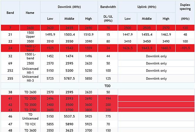
Table 2. Proposed and deployed LTE frequency bands (highlighted bands are referenced in this article) and expected results of commercial base stations
Receiver Design Challenges
Radios and radars have similar basic RF elements for the reception of low-level RF signals: antennas, filters, and low-noise amplifiers (LNA). These generic elements can be assessed against common receiver benchmark performance requirements. Two critical performance requirements that involve interference parameters influencing the receiver sensitivity are blocking and selectivity.
![]()
Figure 1. Generic transceiver block diagram
Blocking is the measure of gain compression at the front-end LNA (preamp) due to a strong signal forcing the LNA into nonlinear compression. In the interest of developing a standard method to assess the coexistence of radar and wireless communications systems, a CW tone can be used to represent the blocking signal (Fig. 2).
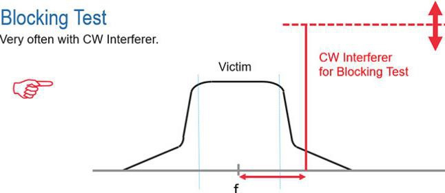
Figure 2.
The CW source should have the ability to generate high power with low phase noise and low harmonics, so the unintentional artifacts of the signal generator do not influence the test results. A standard practice is to determine the frequency and amplitude offsets that degrade the receiver performance. Further, a blocking problem is observed when the frontend LNA reaches a 2 dB compression point (the received signal level reduces by this amount due to the LNA gain compression).
As a figure of merit from the commercial cellular device performance, the example of Table 3 from the 3GPP standards5,6 on Table 7. 4K shows the performance requirements of a cellular base station. In this case, a received signal at 1980 MHz shall not degrade in performance from a CW interference signal 100 dB higher at a frequency of 2000 MHz. That is a fractional bandwidth offset of 1 percent!
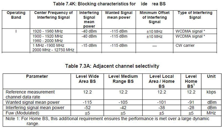
Table 3. Blocking and selectivity performance from 3GPP standards 5,6
Consider the performance of a radar receiver, such as an air and missile defense radar on a ship operating near 3400 MHz, and the potential impact of a base station in close proximity operating in the LTE Band 42/43 (3400 to 3800 MHz). Keep in mind that the radar may have been designed decades before the first cell phone, and the test conditions (signal level and frequency offset) never were considered.
To determine the mitigation distance of a typical 40W terrestrial base station transmitter, you would need to know the radar’s frequency dependent rejection (FDR). Given an example of 40 dB rejection and an expected radar receive signal of -120 dBm at 3.4 GHz, the mitigation distance of the terrestrial network and radar receiver would exceed 10 km.
While these coexistence issues may be resolved within one country by national spectrum policy, sovereign nations around the world may not have similar national policies, thus creating signal conditions that could challenge the performance of a radar receiver in a forward deployment.
Selectivity is the measure of the increase in noise introduced into the receiver front end, while not in nonlinear compression, that will reduce the receiver’s signal-tonoise ratio (SNR). For a selectivity test, a noise type signal is required (Fig. 3). Since the challenge of coexistence in this case is primarily the mix of cellular and radar signals, the noise-like signal used to assess selectivity performance can be a 3GPP test model signal. For this methodology, a selectivity problem occurs when there is a 3dB increase in the SNR bleeding into IF due to adjacent channel noise.
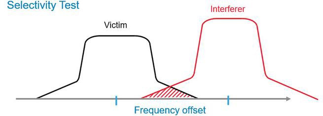
Figure 3.
Like many systems, defense systems have a primary dependency on the GPS system for position, navigation, and timing (PNT). While these systems use robust and powerful correlative receiver processing to recover signals well into the noise, the GPS is received on the surface of the Earth at approximately 2 fW (femtowatts) (-127 dBm). This makes the receiver design susceptible to a blocking signal from nearby transmissions.
The GPS L1 frequency is 1575.42 MHz. A terrestrial base station transmitter at 40 Watts (+46 dBm) is 173 dB stronger than the receiver signal, separated by a small fraction of frequency. At a 50 dB out-of-band signal rejection level, using free space attenuation calculations, the mitigation distance of the transmitter still needs to be approximately 25 km away.
In the U.S., commercial industry took issue with plans by Light Squared 7 (now Ligado Networks) to utilize Band 24 (1600 L-band from Table 2) for terrestrial networks. While the FCC and Ligado Networks have yet to rework those plans, sovereign nations and regulatory authorities have taken notice of the U.S. controversy and developed framework to enable the licensing of this frequency band. This includes the enforcement of more stringent requirements back onto the GPS/GNSS receivers and receiver systems performance.
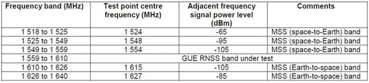
Table 4. Interferer Example for GPS L1 [Source: table 4-2 in EN 303 413]
Test Methodologies And Requirements For GPS
The European Union’s (EU) Radio Equipment Directive (RED) Article 3.2 for all commercial equipment took effect in June 2017. The EN 303 413 standard sets performance limits on receivers for all equipment utilizing GNSS receivers. These limits set blocking performance guidelines primarily in line with the environment of Earth- Satellite and Satellite-Earth communications systems, such as Inmarsat. Table 4 shows the blocking performance requirement for commercial equipment.
In the avionics industry, the Radio Technical Commission for Aeronautic (RTCA) has developed a series of receiver and antenna performance requirements for the use of GNSS systems aboard aircraft (Table 5).
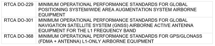
Table 5.
While the RED directive is applied to commercial goods for sale in the EU, it can be used as a benchmark for the U.S. DoD and NATO forces to understand the expected environment of COMSEC assets to be used in sovereign countries with deployed Band 24 networks. As is noted in Table 4, the immunity to a CW interference signal of GPS is +62 dB higher than the expected receiver signal, only 50 MHz away from the L1 center frequency. While commercial use of C/A channel code is narrowband, the L1 military M-code signal (expected for future COMSEC assets) has a much wider channel bandwidth.
The proximity to the blocking signal is much closer to the edge of the M-code signal-occupied channel, potentially creating a greater susceptibility to blocking. Unlike selectivity challenges where correlative processing can recover signals well into the noise, blocking creates a nonlinear impairment to the reception of the signal that cannot be overcome by correlative signal processing.
Radar Spectrum And Test Challenges
When comparing Fig. 4 to Table 1 for the current L-,S-, and C-band communications and considering some of the proposals for 5G frequency utilization between 28 and 72 GHz, spectrum conflicts have the potential to surface at many different frequencies. Considering the number of commercial air traffic control (ATC) radars for civilian airports are similar to ATCs run by the DoD, we will focus on the interactions between Band 7 (Table 2) and ATC radars between 2.7-2.9 GHz, where RF propagation distances are favorable.
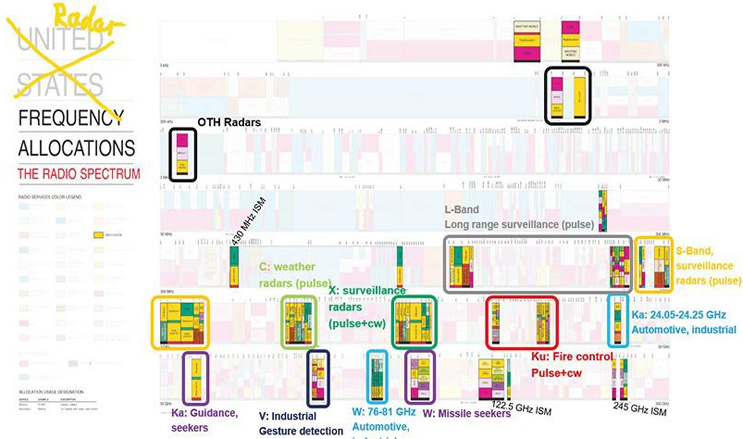
Figure 4. Common radar frequency allocations and intended use
The functional performance of a cooperative radar should be assessed over-the-air (OTA). It is important to ensure that all the radar performance components, including the antenna, filtering, and LNA, are part of the system under test. While the most common tool for assessing a radar’s functional performance is a single dihedral corner reflector, or an array of reflectors at fixed locations, this method is not as ideal as test tools that provide a scaled amplitude number of delayed echoes.
Common tools able to regenerate scaled echoes in an OTA RF environment include digital radio frequency memory (DRFM) systems and radar echo generators (REG, Fig. 5).8,9These tools have the advantage of a controlled delivery of a series of radar echoes, utilizing digital delay taps that are representations of the transmitted radar signal delayed in time and at variable attenuations (representing radar cross sections). This is important for assessing the radar receiver performance, such as delay time (range), signal amplitude, and even the Doppler rate of an echo.
Test Method And Results
While radar receivers may be assessed via many performance parameters, the minimum detectable signal (MDS) is the figure of merit chosen to assess the performance of the radar receiver against blocking and selectivity guidelines.
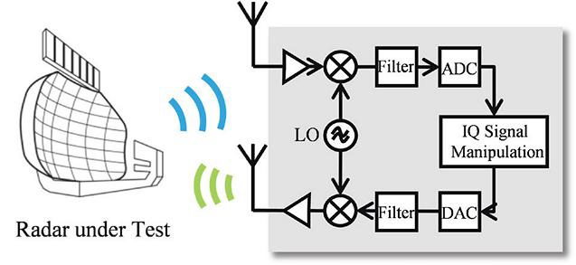
Figure 5. Example of radar echo generator
The performance of a maritime radar was tested to provide an example for demonstrating the test methodology. The results for selectivity demonstrate the frequency and amplitude offsets of the radar’s FDR and were expressed as a function of the fractional bandwidth from the carrier frequency.
In this example, it was not possible to perform the measurements OTA due to licensing restrictions for an OTA transmission, so the results largely demonstrate the selectivity of the radar receiver without the LNA. So, for the purposes of demonstration, the REG was connected directly to the RF input port, while the radar was set to scan mode. This enables the concentric circles to be represented on the radar display, representing the radar echoes at different delay offsets (Fig. 6).
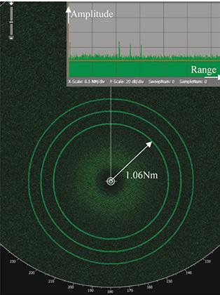
Figure 6. Concentric circles represent a cascade of echo returns
Fig. 6 represents the baseline performance, with three cascading echoes delayed in time and near the sensitivity of the radar. As an out-of-band strong signal is stepped toward the radar’s center frequency, the SNR decreases. Fig. 7 shows the impact of the interference signal on the SNR. While the echoes in the development mode of the radar amplitude-versus-time display remain visible, a user would need to adjust the echogram radar’s noise level to discern any objects on the display.
By following a procedure of increasing amplitude and adjusting the frequency offset, the radar’s FDR are characterized. From the performance data, mitigation distances and offset frequencies are deduced.
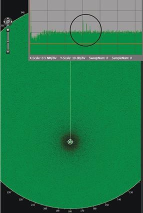
Figure 7. Out-of-band signal increases the noise and desensitizes the echogram
The radar used for this experiment was a commercial marine radar, and it is not representative of a high performance ATC radar. However, if the performance of the FDR for this radar were representative of an ATC radar, and we use a target environment of a Band 7 or Band 41 LTE base station from Table 2, we could develop guidelines for use of the LTE terrestrial stations, as well as the mitigation distance and frequency offset required. Using the FDR performance for this radar as a proxy for the described environment, a Band 41 LTE downlink transmitter at 2690 could not be located within 44 km of an ATC radar operating at 2720 MHz.
Summary
In this article, we discussed a methodology and technique for benchmarking some defense services, such as GPS and radar systems. Based largely in commercial use and dependence on GPS systems, the method invokes several commercial references and standards to guide performance requirements. The testing methodologies and assessment of radars have not yet gained as much attention.
For this study, it was difficult to get information on the blocking sensitivity when not testing in an OTA environment. Gaining access to most of these deployed systems is difficult, and staging them in a proper OTA setting will require coordination with the relevant government agency. Further testing would be beneficial in defining and refining a procedure based on occupied bandwidth and determining the different radars’ FDR.
Studies and recommendations of mitigation distances for all wireless government infrastructure systems and receivers need to be refined. A standard methodology and approach will enable a baseline performance measure, so these issues can receive the necessary attention and potential guidelines on design constraints, as well as assist in determining frequency allocations.
Darren McCarthy is the aerospace and defense technical marketing manager for Rohde & Schwarz America. He has worked in various test and measurement positions for 30+ years including R&D engineer, R&D project manager, product planning, and business and market development. This includes the development of ITU spectrum monitoring systems, COMINT receivers systems, and direct finding subsystems. He also has represented the U.S. as a technical advisor and working group member on several IEC technical committees and working groups for international EMC standards, and currently represents R&S in several industry associations. He holds a BSEE from Northwestern University.
References
- ITU-R Recommendation M.1177-4, Techniques for measurement of unwanted emissions of radar systems, Switzerland (2004)
- ITU-R Recommendation M.1461, Procedures for determining the potential for interference between radars operation in the radiodetermination service and systems in other services, Switzerland (2000)
- ITU-R Recommendation SM.337-6, Frequency and distance separations, Switzerland (2008)
- ITU-R Recommendation P.1546-1, Method for point-to-area predictions for terrestrial services in the frequency range 30 MHz to 3000 MHz, Switzerland (2003)
- 3GPP TS 25.141 V14.1.0, “3rd Generation Partnership Project; Technical Specification Group Radio Access Network; Base Station (BS) conformance testing (FDD), (Release 14)”, Test Specification, Valbonne, France, Dec. 2016
- 3GPP TS 25.104 V14.1.0, “3rd Generation Partnership Project; Technical Specification Group Radio Access Network; Base Station (BS) radio transmission and reception (FDD), (Release 14)”, Technical Specification, Valbonne, France, Dec. 2016
- LightSquared and GPS, https://www.gps.gov/spectrum/lightsquared/, June 20, 2017
- S. Heuel, “Real-time Radar Target Generator”, App. Note 1MA256_0e, Rohde & Schwarz, Germany, Nov. 2014
- K. Shibli, S. Heuel, “Radar Echo Generator”, App. Note 1MA283_0e, Rohde & Schwarz, Germany, Aug. 2016