
How To Select A Power Sensor
By Russel Lindsay, Anritsu Company

A thermal power sensor, looking for love, walks into a bar and immediately sees an antenna sitting alone. The sensor walks up to the antenna and says, “Is it just me, or can you sense the heat between us?” Don’t get it? Well, it’s not that funny, but read on and perhaps it will make more sense.
This final article in our power measurement basics series examines the basic technologies of power sensors, their advantages, and their disadvantages. In our first article, where we discussed the difference between peak and average power sensors, we touched briefly on some of the different types of sensors. Here we will delve deeper into the sensors’ operation and provide insight as to which ones may be more suitable for your applications.
Sensor Technologies
A wide variety of power sensors is available on the market today, each with different capabilities and features. But at the heart of all the instruments, you’ll find power is measured with one of three technologies: thermal sensors, diode sensors, or a receiver (or analyzer). Each technology has its inherent advantages and disadvantages, so it is important to look beyond just frequency and/or dynamic range to pick the one you want. Let’s look at each one individually to gain a better understanding of their capabilities.
Thermal Sensors
There are two common thermal sensor architectures on the market today: bolometer (or thermistor) sensors and thermocouple sensors. Bolometer sensors are usually based in a Wheatstone bridge, which contains a thermistor as one of the elements (as shown in Figure 1).
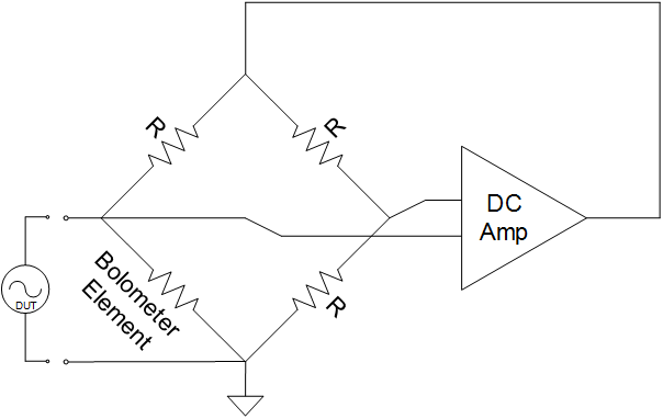
When RF energy is applied to the thermistor, its temperature — and therefore resistance — changes. The feedback loop then adjusts the DC power level delivered to the bridge, in order to maintain balance. The change (specifically, the decrease) in DC power has a direct relationship to the microwave power applied to the thermistor, therefore giving you an accurate power measurement. This relationship is called DC substitution. In most of today’s thermistor-based sensors, there is a second thermistor to detect and compensate for ambient temperature changes. Bolometer sensors were among the first power sensors available. They have the best linearity of all common sensor types, which makes them popular as standards in calibration labs. On the downside, they generally have the lowest dynamic range among common sensors (sometimes only -20 dBm to +10 dBm), and are easily damaged, with a CW burnout of only around +20 dBm.
The second type of thermal sensor, the thermocouple sensor, is based on two scientific principles: the Thomson Effect and the Peltier Effect. Peltier found that the junctions of dissimilar metals were heated or cooled depending upon the direction in which an electrical current passed through them. Thomson predicted that an electromagnetic field would arise within a single conductor whenever a temperature gradient was present. The combination of the Thomson and Peltier Effects is referred to as the Seebeck Effect, which gives us the fundamental physical model of the modern thermocouple detection element.
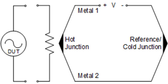
The first advantage to this approach is a very good linear relationship between the change in voltage and the change in power, which results in highly accurate power readings. Second, the thermocouple elements typically have a good resistance to ESD or other transient burnout. Finally, thermocouple detectors measure RMS power and are therefore modulation independent; they will provide accurate average power readings of almost any signal type. But these accurate readings come with some drawbacks.
The change in temperature and corresponding change in voltage requires some settling time before taking a measurement. As a result, thermocouple sensors have much slower measurement speeds than other sensors. They also have rise times in the millisecond range, so they are not suitable for measuring peak or pulse power. Thermocouple sensors also have a higher noise floor, which limits the dynamic range to only around -30 dBm or -35 dBm to +20 dBm, in typical implementations.
Diode Sensors
The second common technology used in power sensors is diode-based sensors. The basic architecture is fairly simple: The RF signal of interest is applied to a load resistor (typically a 50 Ω matching resistor), which is in series with a diode and parallel to a capacitor. As the power rises, the diode controls the current/voltage across the capacitor, which is then read and processed into a power reading.
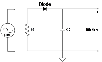
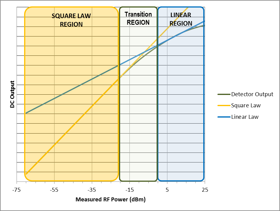
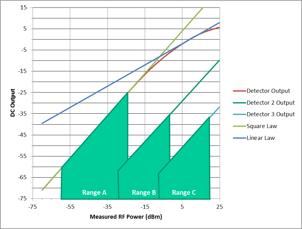
The relationship of the power across the resistor and the voltage across the capacitor can be broken up into three distinct regions:
- Square Law Region — For signals below approximately -20 dBm, the DC output of the circuit is directly proportional to the square of the RF voltage applied. Power readings in the square law region of the diode have a nice linear relationship and are modulation independent.
- Linear Region — Above about 0 dBm and up to about +20 dBm, the DC output voltage is proportional to the peak RF voltage. In this region, the diode acts like a large signal rectifier, charging the capacitor up to the peak RF voltage. Peak sensors will typically work in this region to provide the peak envelope power of the RF signal.
- Transition Region — The region between the square law region and linear region (~-20 dBm to 0 dBm) is called the transition region. In this region, accurate readings depend on careful characterization to provide accurate power readings.
One term you’ll commonly see when researching diode sensors is “true-RMS.” What that term tells you is that all power measurements provided by the sensors are gleaned from readings made in the square law region of the diode. With just one diode, this would limit the dynamic range of the sensor to readings below -20 dBm, which is not sufficient for many RF signals. A user who needs to measure a higher power signal could put an attenuator between the RF source and the sensor, but an external attenuator introduces mismatch uncertainty and frequency dependent characteristics that will negatively impact the accuracy of the power measurement.
To give customers the ability to make true-RMS measurements across a wider dynamic range, many manufacturers have created two-path or three-path diode sensors, which are designed to keep even high-powered signals in the square law region of the diode. Such sensors do this by splitting the signal into two or three paths, each with its own diode preceded by a built-in attenuator.

By designing the attenuator into the circuit, designers are able to minimize mismatch effects and pre-compensate for any linearity deviations. The effect is that all signals are routed through the correct diode path to keep them in the square law region of the diode, thus providing true-RMS, modulation independent, average power readings.
Beyond three-path sensors, you may also see CW diode sensors or peak/pulse diode sensors. A CW sensor likely uses a single-path diode architecture, with algorithms to handle the power relationships of the different diode regions. Peak power sensors require a wideband receiver in order to capture fast changes in the signal. As a result, they also take in more noise, which limits their dynamic range to around -30 dBm.
Unlike thermocouple sensors, which can take some time for heat changes to settle, diodes react almost instantaneously to any change in input voltage. As a result, the measurement speed of diode sensors is basically only limited by the sensor’s ability to process the data. With newer sensors today having better processing technologies, you can find diode sensors with measurement speeds in the thousands and tens of thousands of readings per second. Diode sensors also have fairly good accuracy, but usually not quite as good as thermal sensors. The main reason why someone would choose to use a thermal sensor instead of a diode is the need for greater accuracy (as in the calibration example above).
Receivers
The last type of power measurement technology we’ll discuss is radio receivers. We won’t spend a lot of time on the details, because power measurement typically is not this technology’s primary function. It is generally only found in more expensive equipment, like spectrum analyzers. The reason it is worth mentioning is that these receivers can provide advantages to engineers and testers that are not provided by any power sensors on the market.
First, the measurements taken by radio receivers are frequency dependent, as opposed to most power sensors, which work in the time domain. This means the receivers can be tuned to only measure power within a user-defined frequency range. Thermal and diode sensors are inherently broadband, so they will include power from any frequency, including harmonics or other unwanted signals. The radio receiver can be tuned to filter those unwanted signals out of the final power measurement.
Radio receivers also can have a much lower noise floor than typical thermal or diode sensors, so they can measure signals of much lower power. The best sensors on the market today have a low measurement range of -70 dBm; signals close to the noise floor require a lot of averaging to get a settled reading, and even then the uncertainty goes way up. Receivers can have noise floors well below -100 dBm, so you’ll be able to find and measure many signals that would never register on a thermal or diode sensor.
The major disadvantage to radio receivers (besides the high price of a spectrum analyzer) is the overall accuracy. Radio receivers can have measurement uncertainties greater than ±2 dB. The tune-ability and lower noise floor can help compensate for that (as in the cases mentioned above), but in controlled lab situations, where you may be trying to define a new product’s performance and set specifications, you might be better off with a thermal or diode sensor. Receivers are best suited for simple verification testing (so-called “on/off” testing) in manufacturing lines, or field tests of transmission systems, like wireless backhaul or distributed antenna systems (DAS).
Choose Based On Your Application
So with all that information to consider, which sensor should you buy? The answer may not surprise you: It depends. First, ask yourself what you need to accomplish with your test. Are you creating specifications for a new product? Then maybe accuracy is the most important thing, and a thermal sensor is your best option. Perhaps you’re doing quality checks on finished products; measurement speed and power measurement range capabilities might be your greatest need. In that case, a diode sensor, or maybe even a receiver, might be your best bet. Think beyond just the frequency of your signal, dig into the datasheets, and understand the underlying technology that you’ll rely on. It could mean the difference between good and great products.
For more on power measurement fundamentals, see our other three articles in this series: