
RF Switch Matrix Basics: Configuring And Verifying With Simulation Tools
This is the first in a series of guest columns by Bob Alman of SenarioTek.
RF and microwave switch matrix solutions play a key role in a variety of test systems. At SenarioTek, we design and configure signal routing solutions that are often unique to a specific application. Over the years, we have found some basic steps that help facilitate the design process and ensure that the finished product meets the needs of the test system. This column covers what I believe are the most important initial steps in the process.
Step 1: Determining Your Switch Matrix Configuration Needs
RF switch matrix solutions are found in a wide variety of applications. The preferred configuration depends on the key functions that are required for a particular test solution. For most applications, we have found that there are three common configuration types. It should also be noted that it is not uncommon for us to combine these configuration types based on the specific signal routing needs.
Table 1 highlights each of the configuration types and lists their advantages/disadvantages. The key differentiators for each type are:
- Common highway – This is the simplest design and allows one input to be connected to one output at a time.
- Full access blocking – Each input can be connected to a single output and allows for multiple active channels.
- Full access non-blocking – Using a power divider on the input allows for each input to be sent to any output simultaneously and allows for multiple active channels.
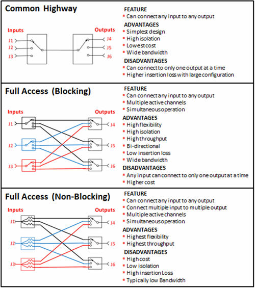
Table 1: Common Switch Matrix Configuration Types
Step 2: Defining The Essential Components
Next, it is important to define the components required for the switch matrix. While switches may be the key component (especially when considering switch life and reliability), consideration is also important for other components, such as cabling, connectors, and any form of signal conditioning that may be needed.
Switching Technologies
There are a number of switching technologies available for consideration. Table 2 highlights these technologies and their relative performance for the different design criteria. Over the years, each of these technologies has improved – more bandwidth, more power handling, less power consumption, etc. The tradeoffs between the competing switch technologies continues to be about the same, only the bar is higher now than it used to be.
At SenarioTek, we have used many of these technologies and closely follow their continued development. For example, silicon on insulator (SOI) was an emerging technology in 2007; today, it is widely available and we often use it in our designs. PIN diode switches keep improving and can now be used in more applications than in the past. Surface mount electromechanical relays are steadily improving, with higher frequencies and better reliability than in the past. MEMS have had a lot of false starts over the last 20 years. While we have yet to use them, the day is not far off. MEMS’ potential for very long operating life is attractive, and we continue to monitor the technology’s progress. Products from different vendors vary in performance, cost, and reliability. We place a high priority in evaluating and choosing components that provide a good balance of price and performance but not at the expense of high reliability.
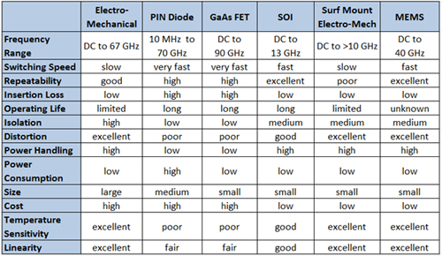
Table 2: Comparing Switching Technologies
Cables
It is not uncommon to have a large number of coaxial cables inside a switch matrix design. The three most common types that most people use are: semi-rigid, flexible, and conformable.
- Semi-rigid cables – Typically are bent only once (if at all) and offer the best performance for high frequency. The cable bends, and bend radius affects the cable’s performance. They may be necessary when phase matching several paths through the matrix and for balanced measurements. Semi-rigid cables usually require mechanical design and are fabricated using computer-controlled machines. Special processing is required to ensure long-term stability, which is especially important in phase-matched systems.
- Flexible cables – Have freedom of movement, which makes assembly much easier. They are lower cost than semi-rigid but also work at lower frequencies.
- Conformable cables – These cables are easy to use and acceptable for most applications. While they do not require as much mechanical engineering design, it is important to remember they cannot be bent more than twice. Highly skilled assemblers are required when conformable cables are used in a switch matrix.
Connectors
The application determines the size/type of connector selected and also the required connector quality ‑ utility grade versus instrument or metrology grade. Connector quality is an important consideration as it is both the first and last point of contact. If you are trying to meet a tight specification, it will be whatever the connector is rated at and then degraded by whatever follows it. You can’t improve VSWR with something on the other side of the connector.
Today, there are many low-cost connectors available on the market. While a connector may be a 50-ohm SMA, it is important to check its specifications for VSWR, insertion loss, etc. In addition, we have seen reliability issues with cheap connectors that are easily damaged by daily wear. Very thin layers of gold will diffuse or wear over time and are not good for military applications that have 20-year life spans.
Signal Conditioning
It’s quite common to add various forms of signal conditioning inside a switch matrix. For some components, special consideration is required for the various states of the component based on changing switching routes. While this could be a paper in itself, the following highlight a few examples:
- Amplifiers – Some amplifiers cannot look into an open circuit. If a hot signal is coming in how is the output handled, high-power terminations, etc.
- Attenuators – Potential calibration concerns with reliability and repeatability.
- Filters – Signals out in reject bands typically bounce off and go somewhere. If you have a power divider, you could be sending signals back that may end up in another channel.
- Power meter and noise sources – Need to be very sure what you are really measuring. We always factor in mismatch uncertainty when using them inside our switch matrix.
- Terminations – Improve isolation. If you don’t want to turn something off, you may need to absorb the power. Digital devices and paths need to be terminated as well.
Step 3: Verifying Your Design With Simulation Tools
At SenarioTek, we run simulations on the majority of our new designs. We use our simulation results to verify our designs before we build them, thus reducing cost and rework time. We have had some remarkable changes in our designs based on our simulation results. At times, we have to tell our customers they are asking for something that can’t be done and we can show them why.
It is important to know the limitations of your simulations and how to interpret results. The designer needs to be familiar with the simulation tool and be able to recognize when the prediction is better than reality. This comes with experience. We typically run simulations on both the entire switch matrix design as well as selected signal paths (figure 1).
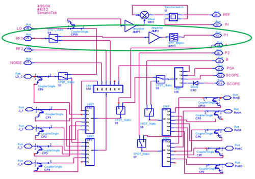
(a) Simulating the entire design
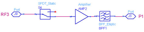
(b) Simulating a selected path
Figure 1: Verifying your switch matrix design before you build it reduces both cost and rework time.
Simulations are only as good as the component models being used. Whenever possible, we use models that are based on actual measured data. At SenarioTek, we have hundreds of component models. Component manufacturers offer datasheets with specifications and graphical data that can be used to build a model of their product. These models are then validated via measurement when we receive the components. Through simulation, we can evaluate competing designs and choose components to optimize performance. We also examine our design’s sensitivity based on the components we are considering.
We find that, if done right, simulations more accurately predict the performance of our design. It tends to be more realistic than the root sum of the squares (RSS) method, which tends to give a more pessimistic result. With simulations, you can analyze your design with more complete vector solutions with many more data points. More complex measurements, such as group delay and noise figure, are easy to determine across wide frequency sweeps. Figure 2 shows an example of the results from one of our designs.

Figure 2: Simulations enable the designer to thoroughly characterize their switch matrix design over a wide range of parameters and measurements.
Conclusion
At SenarioTek, we have hundreds of switch matrix designs in use around the world. Defining the required components for a given application ensures both an optimized design and price. By verifying our designs with simulation tools, we are better able to reliably predict performance prior to sending our quote. We use our simulation to show design advantages, pitfalls, and limitations.
We want to know what you think. What is your favorite switch matrix horror story? What challenges have you encountered with switch matrices? Please post your thoughts in the comments section below.
About The Author
Bob Alman, co-founder and CTO, is responsible for the long-term technical and strategic direction of SenarioTek's products. Along with Simi Ghiasvand, Bob founded SenarioTek in 2003 and has helped build the company from just a few people to where it is today. With more than 25 years of RF and microwave design experience, Bob's knowledge has successfully positioned SenarioTek as a leader in complex switch matrices, thermal vacuum solutions, and innovative calibration solutions.
Bob graduated from the University of Wisconsin with a Bachelor of Science degree in electrical engineering with an emphasis in electromagnetic fields and waves and transmission line theory. Prior to founding SenarioTek, Bob was responsible for the development of Hewlett-Packard/Agilent Technologies RF switches, such as the 8765X SPDT, multiport and matrix switches, and the N181X family of electromechanical switches. During his career, Bob has designed electromechanical, solid-state, and thin-film components covering DC to 70 GHz.