
Application Note: RF Directional Couplers And 3dB Hybrids Overview
By Cobham
Introduction
Couplers and hybrids are devices in which two transmission lines pass close enough to each other for energy propagating on one line to couple to the other line. A 3dB 90° or 180° hybrid splits an input signal into two equal amplitude outputs. A directional coupler normally splits an input signal into two unequal amplitude outputs. This terminology "directional coupler", "90° hybrid", and "180° hybrid" is based on convention. However, the 90° and 180° hybrids could be thought of as 3 dB directional couplers. Despite these similarities, the parameters used to describe signal flow in directional couplers and the application, in actual use, is sufficiently different to warrant separate considerations.
180° Hybrids Functional Description
A 180° hybrid is a reciprocal four-port device which provides two equal amplitude in-phase signals when fed from its sum port (S) and two equal amplitude 180° out-of-phase signals when fed from its difference port (D). Conversely, signals input into ports C and D will add at the sum port (B) and the difference of the two signals will appear at the difference port (A). Figure 1 is a functional diagram which will be used in this article to represent the 180° hybrid. Port B can be considered the sum port and port A is the difference port. Ports A and B and ports C and D are isolated pairs of ports.
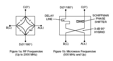
The RF and microwave frequency devices are designed and realized using different theory, techniques, and media. The RF frequency devices utilize coupled wound coils on ferrite cores. The microwave frequency devices are constructed using microstrip or stripline technology and consist of a 3 dB coupler feeding a Schiffman phase shifter and a delay line. Some ultra broadband units utilize a tandem 8.34 dB coupler "Magic T" configuration as shown below in Figure 2.

These three different approaches yield nearly similar results with minor differences that will be discussed later. Utilizing the functional diagrams of Figure 1, we can consider the application of signal at one or more of the ports of the hybrid. The cases that are important to consider are the following:
1. Operation as a power divider - One source operating at ports A, B, C or D.
2. Operation as a power summer - Two sources operating at ports A and B, or C and D.
Click here to download the complete application note in pdf format.