The achievement of high energetic efficiency is recommended not only from an economic point of view, but also as a versatile tool to command the performance of the phone cell, because the energy savings can be applied to one or more other improvements, including:
Larger reception range
Greater transmission speed
Better signal quality (lower BER)
Lower energy consumption on the base station
Increase of the mobile phone battery life
The key element to improving energy efficiency lies, fundamentally, in the use of active antennas. However, duplex operation of cellular phones greatly distorts the desired performance of active antennas. To correct this, one must deploy self-diplexed antennas1, since the diplexer loss irremediably reduces the figure of merit (G/T) and the transmission performance (EIRP).
Here, I will introduce the basic concept of design and performance obtained from a laboratory model front-end with the following features:
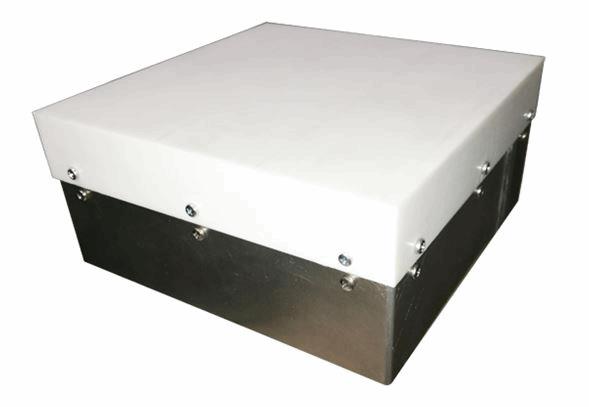
Fig. 1 — Laboratory model of the RF front-endModularity, which allows use in both pico (femto) cells and larger cells with higher modular antenna sizes, however they are reconfigurable (adaptive systems).
Bi-frequency (LTE bands 1 and 7)
In each reception band, two orthogonal beams are produced with ±45 degrees polarization. The transmission is co-polar with one of them; this means the front-end works with six orthogonal beams.
Antenna consisting of a 2x2 array of stacked patches; there are sixteen input ports per frequency band, fed by two Beamforming Networks (BFN) (one per band); the design of these devices leads to a high-performance, self-diplexed antenna with low losses.
Very low noise level LNAs with a built-in filter for protection against the transmitter couple
HPAs capable of handling up to 5W of power.
All these elements are enclosed in an airtight enclosure (IP66) composed of an aluminum box with six miniature snap-on coaxial connectors, as well as a low losses radome (Fig. 1).
Component Design And Results
Fig. 2 — The array antennaThe 2x2 array elements are separated by 90 mm. This space constraint determines the outer dimensions of the box and radome; thus the box is 179 mm, so that large antenna modules can be mounted while keeping the same array constant. This value and the patch sizes of each band are the parameters that determine the directivities of the array, which should be as close as possible in both bands2.
The radiating elements are defined as stacked circular patches, with the patch corresponding to band 7 stacked above the patch belonging to the band 1.
Each patch has four excitation ports, imposed by the self-diplexing BFN design. The two outer excitation ports correspond to Tx, and the remaining two to Rx.
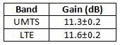
The antenna constitutes an inseparable body with the two BFNs. However, array parameters like matching and radiation patterns have been independently controlled, getting better return loss values of -15dB on all ports, and the following gain values:
BFNs
As in the previous case, the BFNs can be found as stacked plates. The BFN corresponding to the band 7 is designed in Stripline technology, located next to the antenna ground plane; the band 1 BFN is designed in Microstrip technology, stacked under the band 7 BFN.
The connectors used to allow a pressure assembly with the amplifier stage container are SMB.
These circuits are fundamentally responsible for this base station design’s performance. In addition, they constitute the most complex design part and, as such, require as much effort in simulation as in experimental analysis and evaluation.
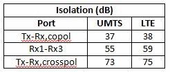
The fundamental parameters of the self-diplexed antenna must be measured in terms of beams isolation:
On the other hand, the merit (G/T) will be fundamentally bounded to the BFN's insertion losses, with the following results:
Amplifiers
The LNAs are defined as two stages with a very low noise transistor, and both stages are separated by a coupled open loop (λ/2) resonators filter. This geometry minimizes the harmful effect of insertion losses on the merit figure (G/T).
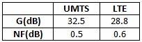
The overall results for these amplifiers are:
The HPAs also consist of 2 stages and are designed for an input between 1 and 10 mW, with an output up to 5W. The total gains and powers obtained are:
*These powers could be increased up to 3 dB by software control if necessary.
In the next version, the six amplifiers will be integrated in a unique box.
Fig. 3 — One of the amplifier boxes
Overall Performance
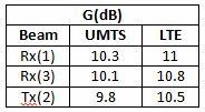
Taking into account the interlayer connection losses, the antenna gain for each of the three radiation beams in the two working bands turns out to be:
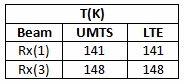
Likewise, the noise temperature at the antenna terminals, for the receiving beams, are:
With this information, plus the noise factor of the LNAs and the output power of the HPAs, the fundamental performance of the system can be determined.
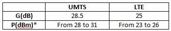
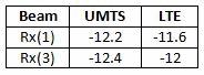
First, the figures of merit G/T (given in dB/K) are:
For the EIRP, the UMTS values obtained are between 37.5 to 40.5 (43.5) dBm, and the values for LTE span from 33 to 36 (39) dBm.
The figure of merit obtained leads to an improvement margin of 13 dB, in the uplink, on the general specification of the 3G and 4G systems. It is clear that this margin can be used to improve one or more of the system's performances by:
Increasing the cell size
Increasing the transmission speed
Improving the transmission quality (lower BER)
Reducing the energy consumption of the mobile phone
Reducing the energy consumption of the base station
To illustrate these possibilities, two extreme situations can be considered:
a) A macro cell is allocated in a place with a very low user density. Incentive for increasing the size of the cell is obvious: reducing the costs of infrastructure deployment. If the 13 dB margin is used to increase the cell size, the surface will be 2.8 times larger than the conventional case. In other words, the uplink range would be increased by 68 percent.
b) Considering the LTE paradigm, basically focused on a deployment of small cells, the 13 dB margin could be entirely used in mobile phone energy saving. In the state of RF emission, this would use only 5 percent of the energy needed with a conventional base station, with the consequence of a dramatic increase in battery duration.
For the downlink case, the technical results are not so spectacular, but the economic impact is strong due to lower energy consumption. This impact is achieved through the use of active antennas, also in transmission. In the case of the laboratory model, the connection losses between the HPA and the antenna are reduced by half. So, the energy savings of our base station compared to a conventional one would be at least 25 percent.
About The Author
Carlos Martín is Ph. D. by Universidad Complutense (Madrid, Spain). He is retired since 2011 and now acts as Scientific and Technical Advisor of ATL Europa. During his 51 years of experience, among other posts, he has been director of the Institute for Teledetection and Telecommunication of the National Council of Research (CSIC) of Spain; director of the center of Research and Technological Development named DETyCOM, AIE (Madrid); and Professor of Applied Electromagnetism, Microwave and Antennas at the University Carlos III of Madrid. Dr. Martín is the author of 130 papers and holds seven patents in microwave and antennas technology.
References
Self diplexing and active radiating elements for active antenna systems. C. Martín, Q. García, N. Mercé, P. Tejedor. ESA-COST223 Workshop on active antennas; Noordwijk (Holanda), 1992.
Patches: the most versatile radiator?. C. Martín, E. Rajo, V. González. Invited Tutorial to IASTED Int. Conference on Advances in communications; Rodas (Grecia), 2001
Microstrip filters for RF/Microwave Applications. Jia-shen G. Hong, M. J. Lancaster. Wiley, 2001.
Newsletter Signup
This website uses cookies to ensure you get the best experience on our website. Learn more