Antenna Products Corp. Optimizes Collinear Dipole Array Antenna Using EM Simulation

 Marlborough, MA -- Antenna Products Corp. announced it improved the performance of a high-frequency collinear dipole array antenna by using MicroStripes electromagnetic (EM) simulation to evaluate a wide range of potential designs.
 Antenna Products Corp. designs antennas that cover the RF spectrum from the kilohertz to gigahertz range and supports mission critical military, air/sea navigation, ILS and voice/data communications applications. The antenna mentioned above was designed for a military application in the 5 to 6 GHz region.
In the past, Joe Ippolito, Engineering Manager for Antenna Products Corp., would have first built and tested a prototype of the antenna based on a simple, first-order approximation computer model. The problem with this approach is that these rudimentary models often leave out significant and surprising effects, and can result in a longer and more expensive prototype development phase. Frequency methods such as the Method of Moments do a good job of simulating wire antennas but do take into account the effects of dielectric materials such as the PCB substrates and the radome.
Ippolito avoided these problems by using MicroStripes electromagnetic analysis software from Flomerics for microwave and antenna design. "We selected MicroStripes because it is very easy to use and because its results closely match physical experiments," Ippolito said. "Before we bought the software we modeled a number of different antennas that we had designed and built in the past. In every case, MicroStripes accurately simulated the performance of the antenna."
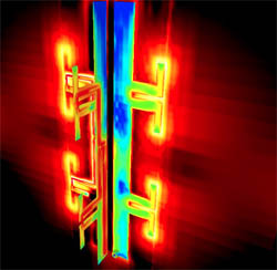
The basic model consists of four PCBs arranged around a central mast at 90° intervals to provide an omnidirectional azimuth pattern. Each board consists of two dipole antennas and an associated microstrip power distribution network. These two-element arrays were stacked to achieve greater directivity and narrower beamwidths.
In the actual antenna each board is connected via a coaxial cable to a 4-way 0° power divider network. This component is located near the base of the antenna and tied directly to the antenna input connector. It was not included in the model as it has no bearing on antenna patterns but its loss along with the associated cables was included in antenna gain estimates.
The simulation injected a broadband pulse into the antenna feed and the time domain response was captured by stepping through the transient phase long enough for it to attenuate to a steady state. Fourier-transformation of this response yielded frequency-domain results across the entire band of the antenna. The model took about 20 minutes to run on a typical Windows PC. The simulation results included surface current density, far-field radiation patterns, and impedance data.
Ippolito then ran a series of iterations in which increasing numbers of two-element arrays or modules were stacked. Ippolito took the simulation results for a two-module array and imported it into a general array factor program that he wrote to evaluate the effects of varying design parameters such as element spacing and orientation. The directivity results of these simulations were graphed versus the number of modules used, in addition to azimuth and elevation patterns for a wide range of antenna designs.
Ippolito picked the three best designs and presented them to the customer and let them select the one that best met their needs. "MicroStripes made it possible to quickly iterate to an optimized design that met all of our customers' demanding requirements," Ippolito concluded. "The antenna has been built, is in use, and has exceeded the customer's expectations."
SOURCE: Flomerics Inc.
